Good evening all,
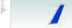
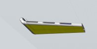
I'm hoping that someone can help with this. I frequently design parts in Moment of Inspiration and then import them into Alibre at STEP, SAT, of 3DM files. They tend to import just fine, no missing faces or anything like that. However, when I try to extrude off of or into the part, I almost always get a non planar face error. The program can't seem to accept that a flat piece or a flat part of a piece is... Well, totally and completely flat. As a result, I can't extrude boss or extrude cut into the new part. Sweeps? Forget about it. I've tried using CAD Exchanger with no success concerning these issues; the non planar face issue persists. I've tried importing in different file formats and with different import settings, and the result is the same. Any ideas on how to correct this so I can actually edit the parts in question? They are pylons for a Trek starship for 3D printing.
Many thanks,
Bob
 I have no idea why they did that. This is something that Support may want to have a look at.
