What's new

Parallel spline lines

jcdammeyer

Senior Member
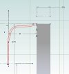
I have a case where I have to make another slightly shorter version of the attached sketch with the reference changed to 18 instead of 21. It's a fairly free form line but the second one needs to be 1mm from the first.
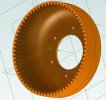
The drawing is then revolved around to make a unique shape cup attached to the part next to it.

The attached was done free hand by eye but I'm wondering if there is a way to do one spline curve and then create a second which is parallel to it 1mm away.
Thanks
John
 

Attachments

  • Shell.jpg
    Shell.jpg
    23.2 KB · Views: 18

MilesH

Alibre Super User
As David says. I do this all the time. Sometimes you may need to make the Spline curve longer and then Trim. You can't extend a Spline using the Extend tool!
 
Last edited:

jcdammeyer

Senior Member
I ended up using a different technique which worked for this. Drew the curve I wanted. Then did a shell for a 1.25mm cup thickness which matches the gear cut using the Python Script. Now to 3D print this one.
 

Attachments

  • CupGear.jpg
    CupGear.jpg
    34.5 KB · Views: 19

MilesH

Alibre Super User
That's good.
One tool which can be very useful with Spline curves is Thin Extrude/Rotate etc.
 

MilesH

Alibre Super User
If you wanted to make a curved plate, for instance, you could draw one edge with a Spline curve then set the plate thickness in the Thin Extrude Boss dialog and Extrude. The advantage being that it's possible to edit the plate thickness. If you Offset a Spline in a Sketch, to get the other edge, you can't edit the offset spacing, you have to start again......
 

jcdammeyer

Senior Member
In line with this same part although perhaps the subject line should change. Look closely at the photo and you can see that the 70T inner gear is mated with the 72T cup gear. The bearings press the round cup into an elliptical shape. The positions of the bearings are based on the formula for an ellipse with the narrow part of the ellipse based on the OD of the 70T gear and the thickness of the root to OD of the cup gear.
And yes. In real life the cup follows the math.

ToothEngagement.jpg

To model this as an assembly requires that the round cup part drawing be squished in the same way the bearings squish the real part. Is there a way to do this in Alibre? I don't need it to turn (although that would be cool) but just to have the cup change shape based on keeping the circumference the same but applying pressure at the two points reducing the diameter there. The other part of the cup would then expand in an elliptical fashion out to the correct diameter.

Is this possible?
 

HaroldL

Alibre Super User
You won't be able to "squish" the part into an oval or elliptical shape. You'll have to create it with that shape. And it's likely that you won't be able to pattern the gear teeth around the elliptical shape although there is a script that patterns along a b-spline so maybe that would be helpful, I haven't tried it so I don't know.
 

jcdammeyer

Senior Member
Thanks. I figured as much. Plotting the gear teeth would be much like plotting a toothed belt running around a number of pulleys along with a belt tensioner and having belt turn with the pulleys.
 

jcdammeyer

Senior Member
It's the design of a harmonic drive with an external wave generator. Normally the drives have the cup gear expanded outwards by the elliptical ball bearing race. This system uses bearings to compress the gear against a fixed gear with 2 less teeth. So my current 3D printed example has 72T and 70T with a 2 tooth difference and therefore 36:1.
 
Top