What's new

Placing holes in a rolled sheet metal part

TimB

Member
Hi,

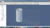
I hope someone can help me. Part of my design is a tube rolled from sheet metal. Using the sheet metal tools in Gemagic design the only way I can make a tube is to use the "lofted" tool specifying the parameters to make the tube I need.

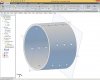
But short of placing holes in the tube while its ub flattened I cannot make the perforations I need. It has to have a large number of holes used as vents all around the diameter.

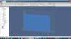
While in Flat pattern mode you can perform no actions like you would say in standard design mode (non sheet mode).

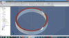
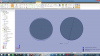
How do I start with a tube and insert the holes? I need to be able to check the part in conjunction with other parts as an assembly so just working in the flat is not going to help.

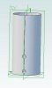
In the example attached I was only able to insert holes on one of the axis planes.
 

Attachments

  • outer shell v2.AD_PRT
    295 KB · Views: 7
  • Sheet tube.JPG
    Sheet tube.JPG
    20 KB · Views: 487

HaroldL

Alibre Super User
You need to use the sheet metal Unbend and Rebend tools to flatten your part then insert the holes and rebend it. If you are placing the holes on the split line then in the flattened state cut a hole on each end of the part.
 

Attachments

  • PERF TUBE.AD_SMP
    369 KB · Views: 9
  • PERF TUBE.png
    PERF TUBE.png
    233.2 KB · Views: 9
  • PERF TUBE flattened.png
    PERF TUBE flattened.png
    226.5 KB · Views: 8

DavidJ

Administrator
Staff member
Though not possible a few versions ago, improvements to the behaviour of the cut function in sheet metal make this fairly simple now - though it can get bogged down rendering if the number of holes becomes vary large. See example attached. I didn't need to unbend/flatten to place the holes, and it will flatten without problem.
 

Attachments

  • Perf Tube Demo.AD_SMP
    788.5 KB · Views: 8
  • PerfTube.jpg
    PerfTube.jpg
    99.1 KB · Views: 11

TimB

Member
Thanks HaroldL

Thats what I was looking for. I had seen inserting Unbend etc into the list when researching on other platforms but not in Geomagic.

I'm at a loss though on how you actually do it. I will have to do some more reading. If you have the time can you tell me where to read up on it in the help file.

Also a big thanks to DavidJ, I'm at a loss though how you did that, any clues on how you did it?

Thanks

Tim
 

DavidJ

Administrator
Staff member
Tim,

I place one hole on a principal plane, selecting the 'through all' option in the sheet metal cut. I then added a circular pattern, followed by a linear pattern (of both original hole and the circular pattern). All done without unfolding or flattening the cylinder.

If you have the latest build of GD, open the file and wind back the dog bone and play back each feature one at a time.
 
Tim,

The first entity feature in a sheetmetal part (AD_SMT) must be a (flat) Flange. It may only be .0005 inch (0.13 mm) long, but it must be there! Your next entity feature can then be a bend that creates your tube. This then creates a true sheetmetal part.

Think about it. When you bend sheetmetal (or bar or plate or...) the material actually forms around the neutral axis. That value (Rn) is given by: Rn = t/(ln((r + t)/r) where "t" is the thickness of the sheet and "r" is the inside radius of the bend. (ln is the natural or Naperian logarithm function.) Inside of the neutral axis all the material is compressed. Outside of the neutral axis all the material is stretched. Thus, all the holes made in the flat pattern are actually semi-elliptical cones in actual shape! This is why it is better to place such holes in the flat pattern.
 

HaroldL

Alibre Super User
TimB,
I found the Unbend/Rebend descriptions in the section on Sheet Metal Features in the User Guide. You can also view some videos in the Geomagic Design Support Video Learning Center.

Not sure which version you have but DavidJ is correct, Alibre, in v12 I think, added a Through All Normal Cut to the sheet metal Cut feature. This allows you to cut through sheet metal without Unbending it first. I'm just in the habit of Unbending to put the holes, cutouts, etc. in the flat pattern then Rebending to the normal state, but I can see that changing.

I also used the sheet metal Lofted Flange which does not have any flat segments in the formed state and Unbends by clicking on the Select All Bends button in the Unbend dialog. However, the method described by Lew is what to do if you don't have the Lofted Flange. Using this method be sure that you do not remove the complete flat segment with a cut. You need some portion of the original flat segment in order for the part to fold up.

A couple of points to look out for: be watchful of which side of the sheet metal tube you place your sketch on and the direction of the cut. If you place the sketch on the Inside and cut outward then the hole will be sized correctly or nearly correctly on the inside face of the tube. If you place a reference plane on the outside surface, sketch and cut inward then the hole will taper inward, as Lew points out, and the hole will be smaller than the dimensioned sketch. In the attached screen shot I have changed the thickness to 6 mm in order to exaggerate the effect.

If you look closely you can see that the hole produced by the sketch on the YZ plane and cut outward, tapers outward or gets larger on the outside of the sheet metal. Where the hole starts on the inside surface it matches the sketch. Likewise on the hole produced by the sketch on Plane 3 cuts inward, it matches the sketch in size and tapers in or gets smaller on the inside surface of the part.
This second screen shot shows the shape and size of the hole in the flat state, one from Cut 2 and one from a hole using the Unbend/Rebend method. The sketch was placed on the inside surface to cut the hole in the flattened state. I placed a sketch of the same size over both holes to show the deformation of the hole in the flat.

The point of all this is that you should be aware of which direction the cut is being performed and to be selective in which face or plane you choose to sketch on.
 

Attachments

  • PERF TUBE sectioned.png
    PERF TUBE sectioned.png
    253.8 KB · Views: 8
  • PERF TUBE Hole Flattened.png
    PERF TUBE Hole Flattened.png
    245.6 KB · Views: 10

TimB

Member
Many thanks HaroldL and others

I will digest that all. The help given so far and using the example part made has enabled me to make the part. :D

Again thanks for the time and effort put into helping me.

Tim
 
Top