What's new

Potential bug in the 2D drawing environment.

Ex Machina

Senior Member
Hey guys,

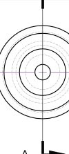
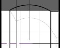
I made this quick and dirty drawing to show in my latest video. It wasn't even annotated properly, but...

I set in my properties that I wanted First Angle projection. That is the ISO standard and is the predominant way in Europe. The two views came in correctly, but when I did the section view, it was projected according to the Third Angle projection. Which is wrong, all views should follow the same projection rule across a document.

I guess this can't be fixed in v26, which I use, anymore, but maybe it could be fixed in an upcoming v27 build. Not many people use 2D drawings anymore but larger companies with multiple departments still use them for archiving and documentation.
 

Attachments

  • Axial Ball Joint Socket.pdf
    1.3 MB · Views: 22

DavidJ

Administrator
Staff member
Sorry - I don't understand.

For section view both the direction of the arrows and the positioning of the view on the sheet is entirely under the control of the user, so I'm not sure what you mean by saying it was projected according to 3rd angle.

Can you elaborate? - or better still submit this to support with full details of what you see as the problem and how you believe it should behave. If there is an ISO or other standard that can be followed, please also quote is.
 

Ex Machina

Senior Member
Yes, that's what is should be. How did you get at that idslk?

P.S. I just re-did it and it projected correctly... I am not even sure what went on there...
1693730870137.pngVery interesting...

I'll look into it more, to see if I can re-create the problem and contact support if I can.
 
Last edited:

Ex Machina

Senior Member
I am not sure Nate. It could've been that. But the two other views are in First Angle projection, already. The way you can tell is by looking at the solid lines only. The two larger circles are very close together. The larger one is the largest diameter of the outer sphere. If you are looking down the sphere, the second largest circle is the top edge of the that exterior sphere, if you're looking down the stem, the second largest circle will be the 10mm OD of the stem. So, it was definitely in First Angle projection before. But I'm not really sure what happened there.

I thought maybe it had to do with which view I defined as front view. The circles is front view and then the side view is the left one, or the longitudinal is the front view and the circles are the right view. But I tried both and now it's doing it correctly. I don't know. Maybe I set it as default and after I restarted it, it straightened itself out.
 

NateLiquidGravity

Alibre Super User
From the looks of it the second largest circle possible would be the ball end which was hidden lines in the pdf - so the initial views were third angle projected. Until I put that horizontal line I couldn't tell.
 

Attachments

  • Screenshot_20230903_100223_Drive.jpg
    Screenshot_20230903_100223_Drive.jpg
    289.6 KB · Views: 6
  • Screenshot_20230903_101621_Photo Editor.jpg
    Screenshot_20230903_101621_Photo Editor.jpg
    59.3 KB · Views: 5
Last edited:

Ex Machina

Senior Member
From the looks of it the second largest circle possible would be the ball end which was hidden lines in the pdf - so the initial views were third angle projected. Until I put that horizontal line I couldn't tell.
Actually now that I look at it again you're probably right. But in any case, that doesn't explain the orientation of the section view. It should be the left view "mirrored".

Anyway, that was a real mess. And I'm even sure what happened there because I can't do it again.

P.S. Oh wait. The 2nd largest SOLID circle is the edge at the top. So, the 2 "regular" views in my original pdf are 1st angle projection, the section is 3rd. Anyway, it works now and I can't get that "bug" to re-appear, so...
1693755523005.png
 

Attachments

  • Axial Ball Joint Socket.AD_PKG
    104.4 KB · Views: 2
Last edited:

HaroldL

Alibre Super User
I think what you experienced could have been a anomaly. But it does point out something that I think should be added or improved for creating section views.

When the section line is drawn and the viewing direction is chosen the section view should be displayed on the correct side of the section line according to the 1st/3rd angle rules. It should not be allowed to be moved to the opposite side of the section line until and unless the 'Align" option (RMB) is deselected. In my opinion, the view should just be placed on the drawing at the correct location and not attached to the cursor. It can be moved to allow for more dimension/detailing space after it is created but cannot be moved or dragged across the section line.

As it is now when the section view is created it is attached to the cursor and the drafter can place it willy-nilly on the drawing which may not adhere to the projection rules.
 

Ex Machina

Senior Member
True Harold. And in fact, that might actually help less experienced engineers who typically don't get enough practice with 2D drawings
 

HaroldL

Alibre Super User
It would help the shop too. It's not fun having someone from the shop come into your office cube to have you explain the drawing view layout.
In my experience I have only had to work off of 1st angle drawings on one or two occasions. I was working as a press brake operator at the time and the part drawing just didn't look right to me. Once I understood it was a 1st angle drawing I could get the orientation of the part correct before I formed them.
 
Top