What's new

Problem with 3D Sketch path Boss Sweep (with binaries)

barrykingwill

Senior Member
Problem with 3D Sketch path Boss Sweep (with binaries)

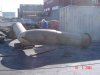
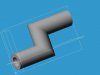
I have this single 3D multibend, multiplane 3D sketch as the sweep path for a (763mm Diameter Pipe) Boss Sweep. It gives me an error saying "can't compute top curve". I cannot see what is wrong. I have tried a different (smaller diameter pipe to extrude but no change)

Either a thin wall sweep or a Solid Boss Sweep would do me fine right now.

Please see photo of pipes from which measurements were taken, as well as the simple Alibre Part attached (or in Binaries)

Any help would be hugely appreciated as I am up against a deadline.

They need drawings of this pipe in order to change the design, and then re-manufacture the new one.

Thanks, Regards

Barry
 

Attachments

  • Multibend Flanged Pipe.jpg
    Multibend Flanged Pipe.jpg
    111.3 KB · Views: 8,145

barrykingwill

Senior Member


For some reason the Part attachment did not get attached. Here it is.

Now I see why. The forum does not allow Part files to be attached. That is weird. OK here it is a step file.

Nope step files are not allowed either. Third time lucky? here is a zip file.

Barry
 

Attachments

  • Pipe3.zip
    56.1 KB · Views: 316

jwknecht

Alibre Super User


Barry,

The pipe appears to be pieced together in sections when it was originally made. So, technically you may not be able to reverse engineer this part with one sweep like you are trying to do. The reason is due to the unnatural sharp bends. When you bend pipe, you typically use a generous bend radius that is about 1.5 times or more the diameter of the pipe. But your pipe seems to be welded together so that rule does not apply. But, for a sweep to work, you can't have the surface wanting to overlap on itself.

If you just want something quick and dirty that somewhat represents the overall shape, you could try modeling the pipe in sections.

Can you post the actual x,y,z locations of your 3D path and also the radii?
 

Gaspar

Alibre Super User


Hi Barry,

I also gave it a try.

I think John is right. A real "one piece" pipe has strainght segments joined to circular "elbows". The segments are always tangent to the elbows.

I tried erasing parts of the 3d sketch to pin point the problem. I ended up with the first two straight sections and still got the error. I applied a 5000 mm fillet and the sweep worked.

I tried a few more times but I couldn't get the rest of the sketch to work.

Anyway, as John said. If your real life pipe is made of sections cut and then welded, you can model that in that exact manner.

I hope your long weekend turns out well :D
 

barrykingwill

Senior Member


Thanks John and Gaspar. Most appeciated, over the weekend and all.

Dave managed to find the problem, and it is relatively simple if you know where to look. Don't ask me how he knew.

The start of the path must not by directly on the plane of the sketch to be swept (although one would think the opposite, ie that it MUST be)

He moved the plane of the circle to be swept by a merely 0.005mm and the sweep worked perfectly.
 

Attachments

  • Nautilus Pipe 4.gif
    Nautilus Pipe 4.gif
    39.4 KB · Views: 8,114
  • Nautilus Pipe 5.gif
    Nautilus Pipe 5.gif
    35.8 KB · Views: 8,113

Gaspar

Alibre Super User


Good thing! The pipe looks really nice 8)

Is this Dave the one Guru Dave from Yahoo?

If he is, I wish he would hang around here some more :wink:
 

barrykingwill

Senior Member


Yip, the same Dave...Guru Dave.

I asked the question on yahoo groups just in case I could catch a few weekend lurkers there too.
 

moyesboy

Alibre Super User


So can I conclude that Alibre does not suffer from the self intersect failure that I see in other cad systems where the swept sketch distance from the sweep axis must be less than the radius of all inside bends of the sweep path?
...if you imagine your sketch as a carboard cutout travelling along a wire bent in the path shape the edge of the cut out must not travel backward as it passes round the bends in the path wire.
 

jwknecht

Alibre Super User
Re:

barrykingwill said:
He moved the plane of the circle to be swept by a merely 0.005mm and the sweep worked perfectly.

Glad to hear that you got it to work and posted the success so that the rest of us will know what to do should we have a similar problem. But that is strange behaviour compared to what the User Guide says:

1. Sketch the closed profile.

2. Sketch the path(s). The path must either start on or pass through the plane of the profile, but is not required to pass through the profile itself. The plane cannot intersect itself.

Perhaps your path was not really on the plane of the profile to begin with (perhaps just a hair off)?
 

Gaspar

Alibre Super User


To add to the mystery, I was able to get Barry's sketch to "work" by erasing elements of the 3d sketch used as path (without moving the plane):

:arrow: When erasing all but the first element, I got the sweep to work, but in a reversed direction (pointing away from the 3d sketch) :? Someone at Yahoo also reported this.

:arrow: When erasing all but the first 2 elements, I got it to work after adding a 5,000 mm fillet. Funny enough I tried this like 4 times and it worked only twice. I didn't spend much time with it, but the difference seemed to be in the order of events.

Good thing is that it worked at the end :D
 

jwknecht

Alibre Super User
Re:

Gaspar said:
:arrow: When erasing all but the first element, I got the sweep to work, but in a reversed direction (pointing away from the 3d sketch) :? Someone at Yahoo also reported this.

I did the same thing and thought it strange, but did not post that result. I wonder if there is something about the "order of events" as you stated. I also did not spend the time to find out. Sounds like a happy ending to the story, the result looks good.
 

Gaspar

Alibre Super User
Re:

jwknecht said:
Sounds like a happy ending to the story, the result looks good.

It does look good. A lot better than the old original pipe in the photo.

That's one good thing about digital models: No rust, no scratches, no missweldings, just our very own little mistakes every once in a while (but we're not telling anybody about them, shhhhh :wink: )
 

barrykingwill

Senior Member
Re:

moyesboy said:
So can I conclude that Alibre does not suffer from the self intersect failure that I see in other cad systems where the swept sketch distance from the sweep axis must be less than the radius of all inside bends of the sweep path?
...if you imagine your sketch as a carboard cutout travelling along a wire bent in the path shape the edge of the cut out must not travel backward as it passes round the bends in the path wire.

As far as I know you can do a 90deg (right angle) corner with a 3D sketch sweep path. That is definitely going back on itself. I have done it with a solid, not with a thin wall, but I suspect you can.
 

jwknecht

Alibre Super User
Re:

barrykingwill said:
As far as I know you can do a 90deg (right angle) corner with a 3D sketch sweep path. That is definitely going back on itself. I have done it with a solid, not with a thin wall, but I suspect you can.

Surprise, it works. I would not have thought that it would. See the pics below.
 

Attachments

  • New Part (2).jpg
    New Part (2).jpg
    32.5 KB · Views: 8,019
  • New Part (2)a.jpg
    New Part (2)a.jpg
    37.3 KB · Views: 8,028

moyesboy

Alibre Super User


Prodesktop succeeds with sharp corners or large radii but not with tight radii that would cause a self intersect. I just wondered if Alibre was the same.
 

jwknecht

Alibre Super User
Re:

moyesboy said:
Prodesktop succeeds with sharp corners or large radii but not with tight radii that would cause a self intersect. I just wondered if Alibre was the same.

I experienced the same on I-deas as you state with Prodesktop. But, it has been awhile since I have tried on I-deas. So, I too was surprised to see Alibre Design do this sweep with a sharp corner.
 
Top