What's new

Problem with inside aligned flange

HaroldL

Alibre Super User
Problem with inside aligned flange

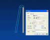
Has anyone experienced this? Check out the pictures and notice how the bend transitions along the base tab as the angle increases.
I've sent in a support incedent report about this, but if anyone else has noticed this. Can anyone say bug?

HaroldL
 

Attachments

  • Form5.GIF
    Form5.GIF
    96.4 KB · Views: 10,173
  • Form3.GIF
    Form3.GIF
    101.7 KB · Views: 10,174
  • Form1.GIF
    Form1.GIF
    96.5 KB · Views: 10,172

jwknecht

Alibre Super User


I guess I would say it is a bug, and that it was not addressed. I am going to look to see if I had previously reported it as a support incident. Even if so, I will open a new incident and refer to your post to prove it has not been addressed. I would recommend that you report it too, and to refer to your post as well.
 

jwknecht

Alibre Super User


I have posted an incident, but the tech never understood the issue. I will repost as the incident was sent to "development", which =s a black hole? :roll:
 

siggy

Senior Member


I'm certainly no sheet metal expert, but isn't the issue here that you have a bend radius that is impossible to create with this material thickness? If you change the bend type to one of the other options you won't get this problem.

If you increase the bend radius to something that equals the material thickness or greater you won't get this problem either.

Robert
 

HaroldL

Alibre Super User


Siggy,

I used the default settings for the part, which gives a bend radius of thickness/2. On some parts I have a radius that is less than that, i.e. .100 thick aluminum at .030 radius.

You are correct though, by selecting the "adjacent" option the "problem" goes away and with the "inside" option it's not quite as noticable.

From the reply I got to my support incedent, it is related to the way the bend is calculated using an ANSI std equation. If I remember correctly from my classroom days, it has to do with inside and outside mold lines.

It would be nice if they had included some sort of explanation on how the bends are calculated for each option. This is one of those issues that needs further clarification in the manual. Alibre was good enough to put an image of the Tab dialog, but when it comes to showing the Flange dialog with its many options all they could come up with is a text-only description of the options. No images of what each option does, or even a screen shot of the dialog. I've noticed that on other commands as well and it is one thing that is starting to really iritate me about the manual. They could have save the printing cost on this one. Even the context "Help" is vague and can be confusing.

I'd better stop now or this will turn into a rant.

HaroldL


Using a bend radius that is equal to or greater than the material thickness is a good design rule of thumb, but I seldom have a customer that specifies corner radius.
From a tool design and build viewpoint, if a bend radius is specified on a drawing I’m dictated to use it. However it is typically drawn with no radius and has a max noted, which allows the tool vendor to design and build whatever they have deemed as economical for manufacturing and maintaining the tool.
I leave the global bend radius at 0.01mm, when I’m “playing” with AD sheetmetal because it reflects what I design and build. But I’ve found it difficult to integrate AD sheetmetal into my design process because I run into too many simple and common sheetmetal features it can’t produce, so I guess AD is not a sheetmetal “expert” either.
 

HaroldL

Alibre Super User


But I’ve found it difficult to integrate AD sheetmetal into my design process because I run into too many simple and common sheetmetal features it can’t produce, so I guess AD is not a sheetmetal “expert” either.

You hit the nail on the head there. Simple and Common features can't be produced. And from the deafening silence coming from Alibre about enhancements to sheetmetal, becoming "expert" may be in the far distant future if at all.

Even the capabilities spreadsheet that Alibre has comparing itself to SW, form features are lacking in sheetmetal. That is one area you would think they would put a lot of programming effort, and sooner rather than later.

A comment from someone at Alibre here in the forums about future capabilities would be nice. How about filling the sheetmetal tool kit. (Anyone listening???)
 

jwknecht

Alibre Super User
Re:

siggy said:
If you increase the bend radius to something that equals the material thickness or greater you won't get this problem either.

Robert


This is not true. The example in my link has the bend radii at the material thickness.

http://www.alibre.com/forum/viewtopic.php?t=741

From the reply I got to my support incedent, it is related to the way the bend is calculated using an ANSI std equation.

I don't buy it! I want to see the calculation and the referenced ANSI standard.

Please don't accept that as a legitimate technical response!

If you use a 90 degree angle, you get the expected result. It is when your angle is not 90 degrees like my post that you get the unexpected result.

Tell me why you would ever use the icon command if it were not intended to be used like the picture on the icon. If you don't know where the corner is going to end up, how will you ever use it to design with?

Come on :!:
 

jwknecht

Alibre Super User
Re:

HaroldL said:
But I’ve found it difficult to integrate AD sheetmetal into my design process because I run into too many simple and common sheetmetal features it can’t produce, so I guess AD is not a sheetmetal “expert” either.

You hit the nail on the head there. Simple and Common features can't be produced. And from the deafening silence coming from Alibre about enhancements to sheetmetal, becoming "expert" may be in the far distant future if at all.

Even the capabilities spreadsheet that Alibre has comparing itself to SW, form features are lacking in sheetmetal. That is one area you would think they would put a lot of programming effort, and sooner rather than later.

A comment from someone at Alibre here in the forums about future capabilities would be nice. How about filling the sheetmetal tool kit. (Anyone listening???)

This is an open call to anyone that wants sheet metal enhancements. I am on the "forum wish list team" and am trying to collect the sheetmetal enhancements. My problem: I am by no means a sheet metal expert and have not used other sheetmetal packages in CAD other than Alibre. So, although there are posted enhancement lists, I cannot understand the meaning of all the requests.

So, by PM or email (jwknecht@candorisdesigns.com) please send to me lists of sheet metal enhancement requests. But, please be sure to elaborate so that all the forum readers will understand the meaning of the requests.

Our plan is to poll or survey the user group to find the most popular requests.
 

HaroldL

Alibre Super User


I'll be submitting another support incedent on this for sure.

After doing some more checking on the flange creation dialog, I found some disturbing results. Take a look at the images to see what is going on.

From what I have seen here the only form you can be 100% sure of is one formed at 90 degrees. Anything other than that you have to be careful
to design your tabs and flanges to allow for the mislocation of the bend. And be careful which alignment option is selected.

I marked up the images so I won't elaborate too much here, I' let the images speak for themselves.

The part was designed with default settings as a 1.000" tab with a 1.000" flange.

HaroldL
 

Attachments

  • adjacent.GIF
    adjacent.GIF
    101.5 KB · Views: 10,054
  • outside.GIF
    outside.GIF
    103.7 KB · Views: 10,048
  • inside.GIF
    inside.GIF
    102.2 KB · Views: 10,049

siggy

Senior Member
Re:

jwknecht said:
siggy said:
If you increase the bend radius to something that equals the material thickness or greater you won't get this problem either.

Robert


This is not true. The example in my link has the bend radii at the material thickness.

I'll be darned - When I tested this out yesterday I would have sworn it worked as I described. But this morning I sure can't reproduce what I thought I saw yesterday.

Can I get away with blaming my error on either old age, poor glasses or a too small computer screen? :?
 

HaroldL

Alibre Super User


After submitting the above three images and filing a support incident, here is the reply:

CHANGES:
AssignedTo >richo <
RecievedDate >1/1/1900 12:00:00 AM<

COMMENTS:
**I will forward this to development as a bug to be fixed in a later version. For now, I suggest adjusting the flange length accordingly through the flange sketch. Sorry for the inconvenience.

Also, I found some information at http://www.engineersedge.com/dist_bend_line.htm that may explain why we are seeing this "problem" in sheetmetal.

I would like to have an explaination from some one (support) at Alibre of how/why the flange option works like it does.
If anyone from Alibre is watching these posts, how about it?

HaroldL
 

jwknecht

Alibre Super User
Re:

HaroldL said:
I would like to have an explaination from some one (support) at Alibre of how/why the flange option works like it does.
If anyone from Alibre is watching these posts, how about it?

HaroldL


Please, oh please :!: We know you are watching :cry:
 

larswebb

Member


Try this, if your bend angle is greater than or less than 90 degrees ALWAYS use Adjacent alignment and Tab as the length type. You can use any bend radius you want.

Larry
 

Attachments

  • Flange test_1.jpg
    Flange test_1.jpg
    34.1 KB · Views: 4,120

HaroldL

Alibre Super User


Try this, if your bend angle is greater than or less than 90 degrees ALWAYS use Adjacent alignment and Tab as the length type. You can use any bend radius you want.

That is what it comes down to. I was hoping the inside and outside alignment options would help in those instances where you need an angle greater than 90 degrees but also need to hold the size of the adjacent flange, including the bend, to a given dimension

By using the Adjacent option, the corresponding flange has to be adjusted to compensate for the material thickness and inside bend radius. That is easy enough to do with the equation editor, but it also requires more work to modify the flange to allow for weld gaps or fit up to adjoining parts.

You have to wonder though, what is the purpose of the inside and outside options if you cannot use them on any form other than 90 degrees without the extra effort involved to make them work. I don't see the value of having them for anything other than 90 degree forms.

Of course, I'm used to using I-DEAS where you work from panels or a solid and choose the surfaces you want to convert to sheetmetal. When you do that you can control the bend placement to where you want it.

HaroldL
 

mub

Member


Hi There!
Of course they understand whats about.
I've just spoken to Scott Erickson including this Topic.
Regarding this problem they're already working on it. He should send me an eMail when they found the solution for. In this case i'll post it as fast as possible within this topic.
Actually Scott said they're planning to release a 2nd servise pack in a couple months. But this is not a promise. They're currently just planning it - but if we're lucky ones also the drawing module performance thing will be fixed.

Just hang in there! :wink:
 

mub

Member
These defects will be adressed in V9.0 service pack 2

Hi all!

Just recieved a document which describes how to handle these things (10 Pages). Scott told me that they will be posting some information in the forum today. :D
 

sae

Member


Hello everyone,

We've been monitoring this discussion and wanted to try to clarify some things about flange creation. One of our sheet metal development specialists spent some time creating a document that explains the methodologies and workflow related to flange creation in Alibre Design. The attached zip file contains the document.

Some if not all of this material will be added to the Help system and User Guide the next available opportunity.

Please take some time to review this and let us know if you have any questions or comments.

Best regards,
Scott
 

Attachments

  • Flanges in Alibre Design 0406.zip
    138 KB · Views: 294
Top