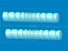
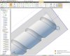
# cylinder dimensions
Diameter = 20
Length = 100
# cutter dimensions
CutterDiameter = 5
# angle to increase by on each pass of the cutter, in degrees
# must be a whole divisor of 180
StepAngle = 10
# total angle of cutting around the cylinder
TotalAngle = 1440
# starting distance from end of cylinder
StartX = 10
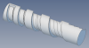
# create the cylinder
P = Part("Cylinder")
CylPlane = P.GetPlane("XY-Plane")
CrossSection = P.AddSketch("Cross-Section", CylPlane)
CrossSection.AddCircle(0,0, Diameter, False)
P.AddExtrudeBoss("Cylinder", CrossSection, Length, False)
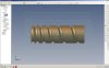
# create the planes
Planes = []
NumPlanes = 180 / StepAngle
for PlaneIndex in range(0, NumPlanes):
Angle = PlaneIndex * StepAngle
Pl = P.AddPlane("P" + str(Angle), P.GetPlane("YZ-Plane"), P.GetAxis("Z-Axis"), Angle)
Planes.append(Pl)
for PlaneIndex in range(0, NumPlanes):
Planes.append(Planes[PlaneIndex])
NumPlanes = NumPlanes * 2
# start of helix has no offset along cylinder
XStep = 0
# create circle sketches then extrude cut 'through all'
for Step in range(0, TotalAngle / StepAngle):
Angle = Step * StepAngle
NormalizedAngle = Angle % 360
XStep += (Angle * 0.001)
if NormalizedAngle < 90:
X = -(StartX + XStep)
Y = Diameter / 2.0
elif NormalizedAngle == 90:
X = -(Diameter / 2.0)
Y = -(StartX + XStep)
elif NormalizedAngle < 180:
X = (StartX + XStep)
Y = -(Diameter / 2.0)
elif NormalizedAngle < 270:
X = -(StartX + XStep)
Y = -(Diameter / 2.0)
elif NormalizedAngle == 270:
X = (Diameter / 2.0)
Y = -(StartX + XStep)
else:
X = (StartX + XStep)
Y = Diameter / 2.0
Sk = P.AddSketch("S" + str(Angle), Planes[Step % NumPlanes])
Sk.AddCircle(X, Y, CutterDiameter, False)
P.AddExtrudeCut("S" + str(Angle), Sk, 0, False, Part.EndCondition.ThroughAll, None, 0, Part.DirectionType.Normal, None, 0, False)