What's new

Projecting a loft past a defined shape

pc-6

Member
I am trying to use 2 known shapes and loft them together, then project past this to come up with a additional shape located outside the two shapes that were lofted together. I have done a simple design using ovals to demonstrate this technique.
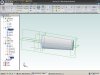
In the screen shot and the attached stp. file you will see oval 1 and 2 lofted together. I have added four 3d sketches past oval 2. These extend out to a 3rd plane which is where I need the final shape.
How do I extrude or loft the existing part out to the third plane labled "Plane 2"?
The actual application for this is a airfoil where I have a cross section for one end and a mid section and need to come up with the section view at the other end.

Thanks all for any help
Leif
 

Attachments

  • loft projection.stp
    47.3 KB · Views: 10
  • Loft projection.JPG
    Loft projection.JPG
    333.1 KB · Views: 28
Leif,

I am colorblind to red, so I may be misinterpreting things here.

(1) Add reference points at the cardinal points of each oval -- you can do that in the appropriate sketch.
(2) Insert axis from reference point to reference point to create a wireframe connecting the cardinal points.
(3) Inset reference points controlled by the appropriate axis and the reference plane upon which you want to project your loft.
(4) Create a new loft based on (A) projecting the "near side" sketch to itself in a new sketch and (B) creating a new sketch on the projection reference plane using the (4) reference points created in step 3.

Does this help? It assumes a linear projection. More complicated projections can be made, but they are much more complicated if the geometry involved is non-canonical.
 

pc-6

Member
Thanks for your thoughts.
Unfortunately this won't work because the actual shape is for an airfoil and is not a straight forward shape such as the ovals in the example. This technique would require an infinite amount of points to be created. I could put in many and join them with a spline, which would get the shape close but not exact. I am after the utmost precision possible, not only because this project requires it, but also I would like to learn the appropriate technique to accomplish this for my own gratification.

Leif
 

HaroldL

Alibre Super User
Leif,
Search the forum for posts from Oldbelt. I remember he has done some lofting of airfoils and posted some examples. He may even log in here and give you a pointer or two. :)
 

Oldbelt

Alibre Super User
Hi Leif something wrong.
 

Attachments

  • Orion-LeftWingpanel-3dgrDih-Cord201mm-Wout-1.jpg
    Orion-LeftWingpanel-3dgrDih-Cord201mm-Wout-1.jpg
    181.7 KB · Views: 34
  • Orion-LeftWingpanel-3dgrDih-Cord201mm-Wout-1.zip
    1.1 MB · Views: 27

pc-6

Member
Thanks old belt.
How did you come up with the sketches for the curving wing tip, sketches 12 to 21? I see the upper surface of these sketches are just arcs. Did you draw them that way or were they projected or calculated from somewhere else?

Leif
 
Top