You are using an out of date browser. It may not display this or other websites correctly.
You should upgrade or use an alternative browser.
You should upgrade or use an alternative browser.
Question For The Sheet Metal Guys
- Thread starter Idahoan
- Start date
Idahoan
Member
I'm somewhat new at doing sheet metal. Most of the time I program my parts from a flat pattern that uses outside bend deduction. I have been playing around with using K-factor just to see if I can get some correlation with the size of the flat pattern. The program that I use to flatten the part and program the NC punch doesn't always play nice with the 3D models, it would be nice to be able to flatten the part in the CAD program and bring it in to the punch program as a 2D file. This is at my day job and we a different CAD program, I thought I would ask here as there are some pretty sharp guys on this forum.
I did find some information that answered my original question that it is the radius of the part and not the punch that is important.
I did find some information that answered my original question that it is the radius of the part and not the punch that is important.
Lew_Merrick
Guest
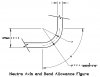
Idahoan -- The "K-Factor" was created by Lockheed during WWII to allow the untutored to generate "loosely accurate" sheetmetal parts for the era's aircraft. Tables of "K-factors: existed well into the 1960's. However using the "Neutral Axis Radius" is far simpler and more accurate. [You have to calculate it anyway to generate the "Lockheed K-Factor" which actually complicates things!]
Attachments

*reads the OP's thread*
*sense's impending (and off-topic) lecture on why Lockheed k-factors are incorrect*
*quietly backs out of thread*
cleverly stated, Sebastion....
....and the very definition of prescience

https://www.merriam-webster.com/dictionary/prescience
Lew_Merrick
Guest
JST
Alibre Super User
I have the gift...
Beans... you know the S/W SHOULD offer the choice.
And you know we know it.
It's one reason I do not use the sheetmetal part very much. It annoys me to have to do things backwards, and I am never certain it was done right.
oldfox
Alibre Super User
I just knew he couldn't stay awayI have the gift...
When calculating K Factor, is the "bend radius" the actual formed radius on the part, or the the tip radius of the punch?
Thanks,
Dave
I don't calculate K-factor (working within Alibre or Solidworks). I use a table (they are all over the internet) for various metals and input that into the CAD, make a flat pattern in the CAD drawing. Maybe it's not the most precise, but I've been getting along with it for years. Don't know if that answers your question or is even close...
Good luck!
Lew_Merrick
Guest
If you look at either of my (above) "previous attachments" orr at the "attachement" here, you may learn something.I don't calculate K-factor (working within Alibre or Solidworks). I use a table (they are all over the internet) for various metals and input that into the CAD, make a flat pattern in the CAD drawing. Maybe it's not the most precise, but I've been getting along with it for years. Don't know if that answers your question or is even close...
Attachments
If you look at either of my (above) "previous attachments" orr at the "attachement" here, you may learn something.
I understand the neutral axis. However, I get along fine with k-factor.
Lew_Merrick
Guest
You may think you do, but the "Lockheedf K factor" is nothing but an inaccurate joke!I understand the neutral axis. However, I get along fine with k-factor.
You may think you do, but the "Lockheedf K factor" is nothing but an inaccurate joke!
Dang! I've never had a problem - going on 30+ years now...
JST
Alibre Super User
It seems the K-factor can be related to a "real" number.
Seems like the K-factor was invented to give shop floor folks, who might likely not be math or trig whizzes, an easy way to get things kinda close for most uses.
You can probably work in a shop for 40 years, and need nothing but that, that and a willingness to adjust a bit by trial and error when some fussy customer wants it closer. I've worked with places like that, and they got the job done.
Problem with it is that in CAD, you don't get to try it, and the dims you come up with are treated like gospel truth. So it seems that the input to the program should be a bit better than that.......
But..... It is what it am......
Lew_Merrick
Guest
Using the Neutral Axis Bend system was something I learned as an Apprentice Machinist more than 50 years ago.Dang! I've never had a problem - going on 30+ years now...