What's new

Re-modeling an STEP file?

PaulProe

Senior Member
Are there any shortcuts or tips when remodeling an STP file? I am doing some 'reverse engineering' and have scanned a part, then converted it to an STP file. I want to remodel the piece in Alibre.

I can go to the STP image, make measurements, and then create a model in Alibre, but this is pretty tedious.

Any tips or suggestions on ways to speed up the process? Some of the parts are relatively complicated castings and it will be a pretty good project to redo them. Maybe I'm spending too much time doing this but I would be much more comfortable having the _PRT file rather than a Modified STP file

Same way with some Solidworks sldprt files or Catia STEP exports. I know the data is accurate, just not 'editable' in Alibre.

Open to any ideas

Thanks

Paul
 

Latitude

Member
Maybe save the step file as an alibre part and bring it in as a part in an assembly and then use that part to project sketches etc?

I will say though I would make sure you actually need to recreate it before you go down that road. Defaturing + recreating only the features that you need to would be much easier if that's an option. Eg. using move face, delete face, etc.
 

OTE_TheMissile

Alibre Super User
What I'd do in this situation is recreate the part within the best of my ability, then start an Assembly with the given model and the one I created constrained to the same spot, so they're merged together. Make one model a different color than the other and you can see where surfaces don't line up & adjust your recreated model accordingly.

I've run into this when we're developing a new product that has to fit into some odd-shaped pocket or body panel on a bike or UTV. The first model I make usually has dimensions, references, and constraints thrown wherever they're needed as we find out what features are more important than others to get it to fit. Gets the job done but usually results in a hopelessly complicated part model that's impossible to make meaningful changes to down the line. Once we're happy with the part's shape and I now know where everything needs to go, I'll make a second model with actual intelligent design practices behind it and use an Assembly of it with my "first draft" dumpster fire to make sure they're identical (or at least close enough), then that second model will go on to have drawings and Assembly models of the final product derived from it.
 

OTE_TheMissile

Alibre Super User
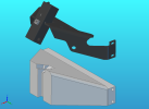
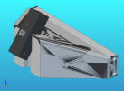
This isn't exactly the same scenario but it illustrates the idea; this is a trailer hitch we make for Indian's big bagger motorcycle (RIVCO part number IC007-V2 [/shameless plug]) that attaches to part of the rear fender/saddlebag support. We were able to figure out where the two pairs of bolts on each side of the factory support that we wanted to use were, we knew what the angle that the square tubing in the middle had to be to fit in the fender, but we wanted to do the entire main frame of the hitch out of one single formed piece of plate (i.e. Sheetmetal). So I drew up a block as a Part that included all the key features, dimensions, and angles, then started making the Sheetmetal model of the hitch plate using numbers I got from that block. Put the two together in an Assembly and just kept tweaking the Sheetmetal model until it matched the Part model.

You can also see the glitchy effect that happens when two surfaces try to occupy the exact same space. In video game development I think it's called "z-fighting", but it comes in handy here to verify that two models you're trying to compare with this method have surfaces in exactly the same position.

part1.pngpart2.png
 
Last edited:
Top