Greetings,
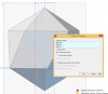
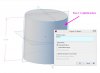
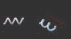
I want to share this tip to those who doesnt know about it. Its been one of the most helpfull "tools" I came across by accident. Dont think this is part of the tutrials? In a nutshell, when you enter the 2d drawing workspace you can use the measurement tool to get refernce geometry from solid parts' edges regardless of which plane you are drawing on. This is a bit hard to explain since Im not familiar with all the english terms. Or perhaps didnt pay enough attention in colege For this reason I dont know what a suitable heading would be. But that reference line is a flat perpendecular projection of the actual edge on the drawing plane. I will add screenshots to make things clearer. This is very helpfull when you want to edit parts in assemblies. Now the problem with this is that the reference geometry dissapears when you click on anything else than the measurement tool if the edge of the solid aint 100% liniar. If the edge is liniar, no matter how its caught up in space in relation to the plane youre drawing on, it is projected and gives you the start and end node of the edge. The last pic is an old one but should make things clear on how usefull it is when designing stuff.
I want to make a request to someone influential at GeoMagicDesign to look into this. It might be a weird drawing style but you will see how awesome it is when you use it. If the reference lines could be stopped from dissapearing it would save a lot of time and effort!?
Any suggestions or comments welcome.
Regards
I want to share this tip to those who doesnt know about it. Its been one of the most helpfull "tools" I came across by accident. Dont think this is part of the tutrials? In a nutshell, when you enter the 2d drawing workspace you can use the measurement tool to get refernce geometry from solid parts' edges regardless of which plane you are drawing on. This is a bit hard to explain since Im not familiar with all the english terms. Or perhaps didnt pay enough attention in colege
For this reason I dont know what a suitable heading would be. But that reference line is a flat perpendecular projection of the actual edge on the drawing plane. I will add screenshots to make things clearer. This is very helpfull when you want to edit parts in assemblies. Now the problem with this is that the reference geometry dissapears when you click on anything else than the measurement tool if the edge of the solid aint 100% liniar. If the edge is liniar, no matter how its caught up in space in relation to the plane youre drawing on, it is projected and gives you the start and end node of the edge. The last pic is an old one but should make things clear on how usefull it is when designing stuff. I want to make a request to someone influential at GeoMagicDesign to look into this. It might be a weird drawing style but you will see how awesome it is when you use it. If the reference lines could be stopped from dissapearing it would save a lot of time and effort!?
Any suggestions or comments welcome.
Regards