What's new

reference lines too long, how to shorten them?

mmtech

Member
Hello,

So I have a model where I needed to make a series of holes, and I made some reference lines to locate these holes.

My reference lines are really, really, long. I'm not sure how I did that... and now I can't figure out how to shorten them.
- Trim does not seem to work
- I'm reticent to remove the reference lines because the location of things depend on them (constraints)

It's not a show stopper, however it's really annoying to zoom in all the time (see below) and I'm trying to progress to beyond amateur operator here.
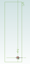
1646666590757.png

This is Alibre Design Expert 23.

Possibly related, when I close this model, Alibre shuts down. Should I be worried about that?

Thanks - and thanks for previous help folks in these forums have given me.
 

DavidJ

Administrator
Staff member
Do you really mean reference lines? The ZX plane and Z axis look oversized - that typically happens if you have a very small feature somewhere 'out in space'.

Reference lines can only be seen in sketch mode - so are not visible in your image.
 

mmtech

Member
I'm not sure...

I do have a small feature out in space - this is what I am reticent to delete. If I could only shrink the length of the line - and I'm having trouble figuring out how to do that.
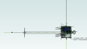
So here's what's making it so big in the horizontal dimension.
You can also see my other problem - I have a really large font in a dimension. Not sure how I did that either.

When I went to delete the long vertical line - Alibre called it a reference line when it warned me that other entities depended on it. And I *did* make some reference lines to locate my holes.

1646668099416.png
Attempting to delete the long, horizontal black line gets me this:
1646668363409.png
If I could just change its length I'd be OK. It has no property of length I can change. I've tried adding a node along that line and trimming to that - doesn't work.

Thanks
 

DavidJ

Administrator
Staff member
Much easier to comment meaningfully if the file is available.

Auto reference lines depend on the 'bounding box' of the part. Reference lines that you add can have end points dragged.
 

DavidJ

Administrator
Staff member
It appears to be something to do with Sketch 2 (Receptacle Holes) - did you have other stuff in that sketch previously?

Any reason why you are doing the holes as assembly features ?
 

HaroldL

Alibre Super User
If you delete the long reference lines and redimension the holes to the origin the Planes will resize to just slightly larger than the enclosure.
Any reason why you are doing the holes as assembly features ?
And as assembly features the holes will not show up in the sheet metal if you create flat patterns for fabrication. That is unless you plan to have them machined into the completed enclosure.
And why don't you just place one hole then use Feature Pattern? That will keep the sketch a lot simpler. If you plan on using the same hole/cutout in other enclosures then create it as a Catalog Feature. You'll need to work in the part model in order use Catalog Features though.
 

mmtech

Member
@HaroldL Ignorance? I learned drafting - literally with pencil and paper... you do not want to know how long ago. Now learning the newfangled ways of 3D models. It's a lot of fun.

My thought was since most of them are not simple holes - they are keyed - they will be machined.

I did not think of the feature pattern. I'll go look up that and Catalog Features.

The holes are offset a little bit because I need them - or the grid of them - in certain locations. Also they are not simply holes, they have notches. The junction box I am replacing did not make use of the keying and thus - a) leaked and b) spun. These will be properly machined and this model is the basis of the drawings for the machine shop.

It is not always clear to me the order in which to do things to get Alibre to be efficient.
 

HaroldL

Alibre Super User
I know how important it is to get replacement enclosures right. I retired from nVent/Hoffman after 42 years with most of them in design, both working on modifying enclosures for customers and in new product development. I also learned drafting on the board but soon transitioned to AutoCAD in technical college while at work I was using I-DEAS Master Drafting. I finished out my time using SolidWorks.

If the holes will be machined then it may be that the keyways will not be square, if you can check with your machine shop to see what tool they will be using and radius the keyway to fit the tool.
1646687975575.png

An alternative is for pilot holes to be machined then use a Greenlee punch or, machine the holes and use a Greenlee nibbler to nibble the keyway.

If you were to have the enclosure manufactured from sheet metal then the cover and body would have to be converted to sheet metal in order to create the flat patterns. So machining, like you're planning, and modifying the assembly level, seems the way to go.

One more point, in order to use Catalog Features you will need to add them at the part level since they are not available for assemblies. You'll need to edit the parts, cover and body, in a separate window to add them.
 

mmtech

Member
Thank you very much. SolidWorks was considered for our office, and it was just too expensive to justify for the amount of work that would be done in 3D modeling vs the budget we have.
 

HaroldL

Alibre Super User
Good thing there is Alibre for the smaller offices. I wouldn't want to hazard a guess at the budget they had for SolidWorks at work. I think they had around 100 seats just in the local plants. But it's a global company so then there's that.
 
Top