wsimonton
Senior Member
I am working on documenting a 1919 Climax Geared Steam Locomotive CN 1551 in Alibre.
I have obtained a copy of the original sheet metal drawings of the Cab from the company which manufactured the sheet metal parts for 1551.
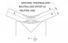
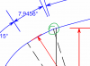
The drawings show the length and radius of the bends which I have reproduced in the 2D drawing attached
The arcs in the drawings are not tangent which Alibre requires in a Contour Flange. When I use Alibre to reproduce the bends the sheet metal part opens up (under bends) after applying the tangent constraints required by Alibre. Is there a way to EASILY calculate (recalculate) the radius of the bends so that the arcs are tangent and Alibre can correctly reproduce the part. Note that the final bend follows the curve of the roof with the same Arc Radius of 150.47"
The 2D DWG has all the defined measurements required from the drawings but note again that the Arcs are not tangent. I have also attached a pdf for those of you who are reluctant to open live files.
I have obtained a copy of the original sheet metal drawings of the Cab from the company which manufactured the sheet metal parts for 1551.
The drawings show the length and radius of the bends which I have reproduced in the 2D drawing attached
The arcs in the drawings are not tangent which Alibre requires in a Contour Flange. When I use Alibre to reproduce the bends the sheet metal part opens up (under bends) after applying the tangent constraints required by Alibre. Is there a way to EASILY calculate (recalculate) the radius of the bends so that the arcs are tangent and Alibre can correctly reproduce the part. Note that the final bend follows the curve of the roof with the same Arc Radius of 150.47"
The 2D DWG has all the defined measurements required from the drawings but note again that the Arcs are not tangent. I have also attached a pdf for those of you who are reluctant to open live files.

.jpg")