danwilley
Member
Hello,
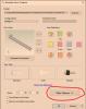
I have a part (bracket) that I modeled using the sheet metal function. The bracket will be made from 1/4" thick steel. I un-bent the part and created a flat drawing with no dimensions and 100% sized. I exported it to a DXF file that will be sent to a laser cutting company. (That flat part will be bent to create the final bracket. See the second screenshot.) The company does not want any dimensional information or other markings. They require only the outline of the part and hole outlines to drive their laser cutting system. I created the basic flat drawing to export but there are two (horizontal) lines on the drawing that show the tab bend margins. How do I remove these two bend lines? I cannot select the two horizontal bend lines to delete them. I have attached two screenshots of the part.
Thanks for your help!
Dan