What's new

Single line DXF

Old Geeser

Senior Member
I am trying to laser cut a cardboard box shape from a dxf file. When I make the .DXF file, I get 2 lines around the periphery in most places instead of 1 They appear to be about .001" apart. Am I doing something wrong when I created the "thin Extrude" or is there a problem with the function? Thanks.
Karl
 

Attachments

  • Organizer Box.AD_PKG
    74.2 KB · Views: 4
  • Organizer Box.dxf
    92 KB · Views: 3

HaroldL

Alibre Super User
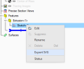
I think it would be better if you exported the sketch as a SVG then convert that to the DXF. That would be the shorter workflow. Otherwise create the part as a Sheet Metal part, if you have that function, and create the dxf from the flat pattern.
 

Old Geeser

Senior Member
Thanks Harold, but I do not see SGV as one of the Export options and I do not have the sheet metal option either. I am using Design version of Alibre.
Karl
 

Old Geeser

Senior Member
Thanks again Harold and I feel I am getting closer. I now get a svg file. However, I am still not quite there. What program do you recommend to convert it to dxf. I tried loading it in freeCad and it didn't display anything and gave me lots of error messages. I looked at the binary file and it looks like it is organized into blocks, each block is fifty bytes long. A sketch of 3 lines, generates 14 blocks. That's as far as I can go without help. The format of those blocks would be a big help. Any direction you can direct me to would be appreciated.
Karl
 

HaroldL

Alibre Super User
I think this has come up before and someone suggested an online converter. I used Inkscape to open the SVG and save it out as a R14 DXF. I was able to open it in Alibre and it came in as several blocks. After exploding the blocks I was able to apply a dimension to check the size against your original file and it was the same.

Here is the dxf:
 

Attachments

  • boxSketch.dxf
    7.1 KB · Views: 2

DavidJ

Administrator
Staff member
Thin extrude will create thickness, not a line.

Could you just sketch this directly in the drawing workspace? (use 'sketch on sheet') - you can even copy from the part sketch and paste into drawing sheet (but be careful of scale).
 

Old Geeser

Senior Member
Thanks David. But for some reason I am just not comfortable sketching in the drawing workspace.
But Harold gave me the info I needed to use the .svg output. I spend all day yesterday writing a reader for the .svg output. Lucky for me the file format is ascii text and easily read. For an 80 year old to spend a 12 hour day coding is lots of fun anymore. I got it reading lines & circles now and am on to partial arcs. It outputs the start & end points and the radius. Where as .dxf requires center point, beginning angle and ending angle, & I need to figure a way to select between the 2 possible solutions. So, I've got my work cut out for me for today (and maybe more). Another interesting point is that the data is output at 96X the scale. I wonder if files always use this same scale factor?
Thanks again, Harold.
 

DavidJ

Administrator
Staff member
I seem to recall the SVG uses 96 DPI, there's a thread mentioning this somewhere on the forum.
 

srjacob

Senior Member
I have a dxf file, but when I open it in Alibre, it gets open into the drawing workspace. How do I get it to open in the part workspace (I want to create a part out of it).

Thanks, Steve
 

NateLiquidGravity

Alibre Super User
Imported drawing to part:
Open the file.
You edit the sketch in the drawing.
Copy the sketch entities.
Open the part.
Start a sketch.
Paste the sketch entities.

The reverse also works. You can copy and paste from part sketch to drawing sketch.
 

Old Geeser

Senior Member
First, thanks for the help you gave me earlier in getting single line data using the "export SVG" function. I have managed to parse out the line and circle information. However, I have spent the last week trying to understand the arc data. It contains 2 points (start & end) and the radius. I know that there are two possible circles that will pass through the points, and a given radius. I seem to need one more piece of information in order to come to one solution. I tried all arcs in a counterclockwise direction from first point to second point. It did not work. Can anyone point me in the direction I need to look?
Thanks
Karl
 

Old Geeser

Senior Member
Thanks to all who helped me with this, especially Harold who put me onto the SVG file. I finally, after much research, have found the missing info that I was searching for. It seems that all partial arcs are ccw unless the sweep flag is set. Bingo, it seems to work just fine.
Karl
 
Top