Just to be clear, the way it works today is not "broken". You clearly would like it to work differently, which I understand. We can look into what it might take to do this. Nothing is tens of minutes, and rarely hours.
Also, there are a few things to keep in mind. What if you project a linear edge and you create another line that has an equal constraint to the projected edge, and then other figures. You place a dimension on some other figure, and now everything has to scale. But the projected line nor its equal constraint cousin can scale. So now what? Do we not scale anything? Try to only scale what can be moved?
When we do scale, where to we scale from? If you dimension a line, then the centerpoint of the line might be the scaling zero, but what if you dimension between two lines?
It's not as straightforward as you might think. I understand it feels like it's so simple, but there are some corner cases and gotchas which, as usual, take 80% of the time.
In any case, we can take a look. If it is in fact simple we can consider it.
Max, thanks for the response. I think it is completely awesome that you care enough to be here fielding issues and concerns of customers.
Given, one draws ANY sketch without dimensions; and say there are x entities in the sketch. Those entities may or may not be physically connected but all of the entities fit in the displayed view. It is reasonable to assume that those entities are arranged the way the author intends them. Placing a dimension on any one of those objects should, in no way disturb the arrangement of the entities in the sketch.
The only way I see to not disturb the sketch is to scale entities. The scaling should be ALWAYS; after all, the author did take the time to draw the shape as they wished it to be. It is improbable that one would go through the rigors of drawing a desired shape to then place a dimension on one of the entities in the shape, and have the shape completely change. At least that is MHO.
Please be patient with me, I am not mechanical designer, drafter, 3d person, etc. I know VERY little about 3d/mechanical design. I've never made a product with any package, SW, Alibre, Turbocad, Freecad or any other. I am just a guys than owns engineering software and like to play with it when I am not golfing. I do however have a AS in Math and Computer Science, a BS & MS in Electrical Engineering, and will be starting work on a PhD in EE in the fall. So the example(s) you give elude me...
Further, my work background is that I have been a computer/IT guy ALL of my life, since age 14--age is 52 now. A do know how to program in C, C++, C#, and other languages, C++ being my preferred. I give my background to let you know I am not an expert or even an neophyte in mechanical design. But some things just make sense.
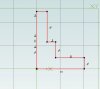
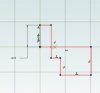
So I am attaching two pictures. One with the shape I want; and one after I dimension the circle. The only circumstance that should change this shape is if there were already any dimensions on the sketch. But, as initially stated I am talking about placing the FIRST dim in the sketch so the aforementioned circumstance would not exist.


This shape should not change when the first dim is added. We have 4 lines and a circle... as follow
entity dim
line1 a
line2 b
line3 c
line4 d
circle1 e
Assume that e=.1643 and then I dim it to 100... Well then the scaling factor is 100/.1643=608.6427; so to keep the shape the same would mean
entity dim
line1 a*608.6427
line2 b*608.6427
line3 c*608.6427
line4 d*608.6427
circle1 100
I don't think there is any other way to ensure that the shape is preserved. Again, your examples bewilder me somewhat; perhaps it is just my lack of understanding of this domain. But, that is how it works in SW. ...I supposed you'd have to work out the coordinates as well but I don't see that as being overly complicated either.