What's new

Sloping stair railing

Lukin

Member
Hello forum members,

I am new to Alibre Design and I like this SW very much, I thank all the people who are involved in its development.

Now to the question:

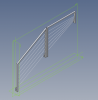
I would like to ask if you have any tips on how to simplify the modeling of a sloping stair railing, so that it is composed of individual components (posts, handrail, infill rods).

I was used to doing this in a so-called frame construction, and changing the angle of the railing or some dimensions in the assembly was easy. Unfortunately, Alibre does not have this function yet, so I want to ask if anyone has any tips that would guarantee that changing a dimension in the assembly will not be so complicated and it will not be necessary to adjust all components (cutting angles of individual handrails tubes, rods often lead through the posts - holes at a certain angle).

Thank you for any tips and also thanks for the great SW Alibre.

Best regards Lukas.
 

sbeamers

Member
If I were doing a project like that my go to tool would be configurations in each of the individual components (posts, handrail, etc) with the assumption that I know what the dimensional values will be when assembled. (Even if I didn't, I would modify a part and add configurations as needed.) For instance, if I needed six 3 ft posts and 4 3 1/2 ft posts, I would use configurations in a single model and then select the needed configuration at assembly time.
 

JST

Alibre Super User
Stair railings are just a problem. My customers always seem to want odd dimensions and attachments, different in different places.

The key issue I have found is to have the fewest separate parts to begin with. Then you re-use parts in similar places, so only one may need to be changed. One post for this angle of stair, so when the hole through changes, one change does all those posts.

Using subassemblies etc, all the standard tricks.

It may be that Global Parameters can be used to get angles from the stairway beams to bevel pipe ends, or put through holes, etc. I have not done anything with that myself, because I do not usually have more than one related stairway to deal with, and it looks like more work for little if any benefit.
 

Hunter

Senior Member
I make use of Global Parameters and a top-down design approach. Also configurations.

You'll have to try a few methods to see what works best for you. If it's a once off, I'd use the top down approach.
 

Lukin

Member
Hello to everybody,

I would like to thank you for your comments so far.

HaroldL, do you have any more types? Which would be directly related to the Alibre version?

JST, Hunter, sbeamers do you have a specific model or picture for inspiration that you would not mind providing?

For the sake of clarity, I am now working on such a model and I am annoyed that when I decide to change the spacing of the posts, for example, I have to change the angles of inclination of all holes (because I want to have the railing divided into individual parts and not have it as one part).

And there are many types, different slopes, sometimes square columns, other circular columns and other variants.
 

Attachments

  • Obr. 01.PNG
    Obr. 01.PNG
    91.3 KB · Views: 32
Last edited:

Lukin

Member
Dear Hunter,

that'd be amazing.

Thanks, it looks like the community of experienced Alibre users is great.

Note:
I apologize for my comment in my native language, I use a translator, which caused a bit of confusion. As soon as I noticed the confusion, I decided to edit the previous comment into English, because I think it's better for everyone.

However, you answered despite the "problems" mentioned above, that's great.
 
Last edited:

HaroldL

Alibre Super User
HaroldL, do you have any more types?
I asked about your version of Alibre because configurations are only available in AD Expert. And since that is what you have, you have all the bells and whistles Alibre has to offer, so far.
 

JST

Alibre Super User
If you have individual sections, then it seems as if you do not need to have the holes, unless this is "artistic" railing where the design requires it. Or perhaps if the cross-bars are not solid bars, but instead are metal cables, which need to be tightened.

I usually am working with ordinary industrial railing, so the cross-bars would be plain bars or tube simply welded to the uprights, without holes. Then I can simply give the dimensions for welding, and the lengths of the parts, plus any angle cuts necessary.

It is also not clear to me why the holes need to go completely through the tube. Most railing is made with tubing, either round or square, for the posts. If the sections are individual, and a more rigid bar is used, not metal cable, then holes that do not go completely through, but only go through one wall of the vertical tube, would be better, it seems. They would also fit at any reasonable angle, especially if the hole were beveled somewhat. Only for very steep angles there might be a need for a different hole. The rods that go in the holes would be put in place before the section is welded together.
 

HaroldL

Alibre Super User
For the sake of clarity, I am now working on such a model and I am annoyed that when I decide to change the spacing of the posts, for example, I have to change the angles of inclination of all holes (because I want to have the railing divided into individual parts and not have it as one part).
This sounds like something that might be handled by the equation editor or WizoGrid. (Although I am not an expert in either there are some on the forum who are and could give some pointers.) Once the equations are set up any change in spacing would/could update the angle of incidence.
 

Hunter

Senior Member
So hear is a VERY basic model showing one way to use a Global Parameter (GP) file and linking part and assembly parameters to the GP parameters. It requires a bit of planning, since everything has to driven from the GP file.

Below pics shows a staircase with some arbitrary values (some of them not practical, but just to illustrate the principle). You simply change the parameters in the GP file, click on "Update Designs" and the staircase updates.

You can change 5 staircase parameters, but you can ofcourse add more, link more files, etc. Although I didn't do it, you can also make use of configurations within the assembly and/or parameters, and link different configurations' values to the GP file and within the assembly file.
upload_2021-2-14_11-30-25.pngupload_2021-2-14_11-25-27.png upload_2021-2-14_11-25-40.png upload_2021-2-14_11-25-54.png upload_2021-2-14_11-30-25.png
 

Attachments

  • Staircase Assy.AD_PKG
    51.1 KB · Views: 3

NateLiquidGravity

Alibre Super User
With the addition of assembly level sketches it is possible to reference the length of a part to calculate the number of spindles needed.

Create an assembly sketch on a plane parallel to the stairway.
Dimension the length of the stair rail part's edge making sure to check the box allowing it to be a parameter.
Create a new scale parameter that gets the integer of the absolute value of the division of the length parameter by the spindle center to center distance. Example: int(abs(D4/D5))
Use that scale parameter for your pattern count.
 

Lukin

Member
Hello Hunter,

thank you for your time and for providing inspiration.

The advantage of your design is that you count on a certain regularity. In reality, however, it is sometimes necessary to improvise (small deviations in the dimensions of the stairs, etc.). Then it will be important to solve the holes in the posts (sometimes people demand a hole to through, sometimes only from one side). However, this will be mainly for me an it's my problem. I can't ask for everything from you, even if you're great.

I would like to thank you once again for showing me a possible way (I think if I use a few more mathematical functions - HaroldL wrote about this, at least I think. I could achieve a good result) and sacrifice a moment of my precious time. It seems like a great idea.

Thanks to others for their observations and ideas.

Best regards Lukin.
 

Lukin

Member
If you have individual sections, then it seems as if you do not need to have the holes, unless this is "artistic" railing where the design requires it. Or perhaps if the cross-bars are not solid bars, but instead are metal cables, which need to be tightened.

I usually am working with ordinary industrial railing, so the cross-bars would be plain bars or tube simply welded to the uprights, without holes. Then I can simply give the dimensions for welding, and the lengths of the parts, plus any angle cuts necessary.

It is also not clear to me why the holes need to go completely through the tube. Most railing is made with tubing, either round or square, for the posts. If the sections are individual, and a more rigid bar is used, not metal cable, then holes that do not go completely through, but only go through one wall of the vertical tube, would be better, it seems. They would also fit at any reasonable angle, especially if the hole were beveled somewhat. Only for very steep angles there might be a need for a different hole. The rods that go in the holes would be put in place before the section is welded together.

I completely agree with you. But this is only an isolated case. Other times it may be different and holes may be needed in the individual components.

Maybe I could have given a different picture as an example, but now I have just developed this version. I didn't realize it could be confusing. I am sorry.

And thank you for your tips.
 

Lukin

Member
With the addition of assembly level sketches it is possible to reference the length of a part to calculate the number of spindles needed.

Create an assembly sketch on a plane parallel to the stairway.
Dimension the length of the stair rail part's edge making sure to check the box allowing it to be a parameter.
Create a new scale parameter that gets the integer of the absolute value of the division of the length parameter by the spindle center to center distance. Example: int(abs(D4/D5))
Use that scale parameter for your pattern count.
Great idea.

Thank you.
 
Top