What's new

Springs in assemblies

JordanCClark

Alibre Super User
While the helix is great for making springs, sometimes you'd like to see one compress or extend whilst constrained within the assembly. Since I just had to do one in SolidWorks, I though I'd do one up in GM and share it here.

I'll do up a tutorial when time allows, but don't expect it to be too soon. :lol:
 

Attachments

  • Spring.AD_PKG
    47.5 KB · Views: 46
Jordan,

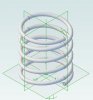
I believe I know how you accomplished this (but I shan't have time to review things until sometime next week) and it is a non-trivial solution. One thing lacking in such an approach (and endemic in the SolidWorks and ProE/CREO approaches) is that the (mean, inner, and outer) diameters of a compression coil spring increase as the length decreases. My "solution" (posted over at GrabCAD) is to create configurations for Free Length, L1 compression and L2 compression that may easily be "swapped out" to drive assembly models. No, I have not taken it to the point of having several intermediate lengths developed.

What is truly lacking here is a combination of advanced constraints in conjunction with project level equation association. With such connectivity would come the ability to truly model this (and other) truly parametric relationships of components within an assembly. I believe that 3D Systems (like Alibre before them) have made a mistake in not carrying advanced constraints to their logical conclusion. Once implemented, dynamic analysis (more accurately called kinematic analysis becomes nearly trivial. (This is why my compression spring design system declares the Spring_Rate as part of the Equation Editor definitions.) Constraints are only a set of linked-list associations after all...

Now, mind you, I look forward to seeing your approach here. Coming up with connectivities that allow "following" of things such as springs, pneumatic cylinders, and the like at the assembly level easily fall into the good things category!
 

JordanCClark

Alibre Super User
Thanks, Lew.

To be honest, I wasn't looking for something strictly accurate as I was looking for something to use in an animation. :lol:

I completely agree about needing advance constraints and global associations in GM. Been a request for as long as I can remember...

EDIT: Perhaps designing the spring top-down may "sorta" work, but as i recall there were some crazy things that could happen in the constraints between the assembly and the sketch...
 
Hi Jordan,

The programmers and tech support people at the old Generic Software Company always used to say, There are the few -- and then there's Lew! -- a tradition I continue...

I believe (without having had to time to examine things properly) that your approach involves designing a spring component within the context of an assembly such that you can assign bounding planes an associativity to mating assembly geometry and use that equation editor value to control the height of the helix in the spring component's part file. It should be obvious that you have to insure that the associated values do not "crash" the spring or the results can be quite "humorous." (A situation with which, you understand, I am entirely unfamiliar! Right?)
 

JordanCClark

Alibre Super User
Close. Very close Indeed! :D

The Eq Editor is used in defining the wire OD and spring OD. Admittedly, there's a Length entry in the Assembly, but, in fact, it's unused. I just forgot to take it back out. A bit of a red herring... :lol:

The spring "sections" may be viewed as one half-coil:


The spring "proper" is put together using the usual Mates and Aligns:


Highlighted section's planes are constrained to be parallel (I used Angle, but Orient should work as well):


One or two more constraints to keep it from spinning and to keep the "top" of the spring on the axis.
 

Attachments

  • 2014-09-08_5-25-09.jpg
    2014-09-08_5-25-09.jpg
    43.8 KB · Views: 10
  • 2014-09-08_5-31-32.jpg
    2014-09-08_5-31-32.jpg
    47.2 KB · Views: 12
  • 2014-09-08_5-36-35.jpg
    2014-09-08_5-36-35.jpg
    99.6 KB · Views: 13
Jordan,

What your model shows is known as a Closed & Squared type of spring. The squared coil usually spans between 200° and 270° depending on the wire's diameter and the spring index (the ratio of the mean diameter to the spring's wire diameter) when then helixes to 1 wire diameter out to one or two full "turns" from the start of the (revolved) base. The intermediate helix is one where the helix height is the (current) overall height - (2 or 4) * wire diameter over a total number of "turns" defined by Spring Total Number of Coils - (2 or 4). The final squared end is then merely the reverse of the initial squared end.

Thus, so long as you are defining such a spring in the context of an assembly, you "merely" use the separation distance defining the spring top and spring base reference planes to control everything (with an offset distance equal to the wire diameter/2). Yes, this approach gives you inflections in the transitions from base revolve and the squared end and again between the squared end run-out and the active coils, but this is usually very minor and not visible unless one is zoomed in fairly closely. Also, the "wire" is elliptical (by the cosine of the helix angle in the derived coils (caused by using Project to Sketch), but that is also very minor and invisible unless one is tightly zoomed in.

???
 

RocketNut

Alibre Super User
I don't know about GM Simulate package since I don't have it. I would think tho any simulation of a spring would take an extremely long time due to the cpu overhead needed to redraw the spring helix each time. Then there is GM out of the blue crashing would only increase the time by a factor of 20%. Thus meaning you would have to have a dedicated machine to run the simulation because it would take days ( if not weeks) to run the simulate.

RocketNut
 
Top