What's new

Starting a New Thread for the Crib Sheet and Bolts, Screws, and Studs

silver2row

Senior Member
Hello,

As some of you know, I am a fanatic regarding bolts in general. As I have learned some movements and rules in Alibre, I have also come across some distinct errors in the software...

Please hear me out here.

So, I make a cylinder out of an extruded circle. I then guide my line making behavior in the 2D sketch. I make a triangle or a quadrilateral with unequal sides at 60 degrees for the...oh. I think I just figured out the issue(s)...

I was making my diagonal lines 60 degrees instead of the top line to be 60 degrees with the parallel line to the top line (Pitch/4).

Blah...

Seth

P.S. I need to watch the videos again and rehearse. If you want to reply, okay. If not, okay too.
 

silver2row

Senior Member
Dang it,

Okay...so. How would I make the top line 60 degrees, i.e. is that just by chance or is it by equal sides of the diagonal lines?

Seth
 

silver2row

Senior Member
Hello...I will watch the older video again and watch the new video too. Thank you!

Seth

P.S. First off, you rule. That is way more in depth than I figured I needed to go. Thank you...I saw the second video and yes, I was wrong. The two diagonal faces on the sketch of the quadrilateral both need to be altered so the top line has a 60 degree face. Okay. Got it. I will attempt the second video again and return service. Thank you again and again...
 
Last edited:

silver2row

Senior Member
@HaroldL ,

Seth here. Okay, so...

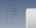
1. Here is a photo of the video:

From_Video_D5_MM.png

Is D6 = 5 because of the quadrilateral being one millimeter in height?

Seth

P.S. The reason I ask is this idea: I have a bolt with a 20mm diameter and 50mm length. I am following along in the summary video. I got that D4 = 6 because of the radius of the bolt is 6mm due to it being a 12mm in diameter bolt, right?

So, I will attempt to adjust the 2.5mm/4 for the parallel line to the 60 degree line but what is D6 in relation to size and diameter?
 

silver2row

Senior Member
Also,

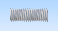
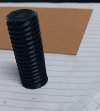
I tried to follow along. I came up with some 20mm diameter * 2.5mm pitch * 50mm length bolt. Here is the outcome. It is not correct, i.e. as I am working towards the full diameter of 20mm and my bolt falls short of such parameters. I will try the video again.

Seth

P.S. Oh! The photo of the bolt. It is near perfect. I could not figure out how to make the D6 have a value from the photo in my last post. In any light, check out my building habits!

Bolt_006.png
 

HaroldL

Alibre Super User
So, I will attempt to adjust the 2.5mm/4 for the parallel line to the 60 degree line but what is D6 in relation to size and diameter?

In the video I state the the D6 is the MINOR RADIUS of the thread. That is something you'll need to look up for the thread you are creating. (the actual dimension for 12x1.75 pitch is closer to 5.053 but that should come from the crib sheet to make sure. I just dimensioned it at 5 to illustrate the need for the dimension.)

I came up with some 20mm diameter * 2.5mm pitch * 50mm length bolt.
You will need to find the minor radius for this new thread and dimension the bottom of the profile accordingly.
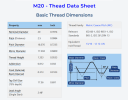
Here is some data for the M20 x2.5 thread that should help. I got it from https://www.machiningdoctor.com/threadinfo/?tid=1027

1707279586677.png
 

silver2row

Senior Member
Yes sir...I understand now. I know there are basics and then OEM parts too. I understand that there are specific bolts that are not standard types or sizes now.

I found a good site called bolt depot. Anyway, they have some ideas they have made known... Thank you.

Seth

P.S. I will read more into how to mfg. a bolt in time outside of the software side of Alibre Atom3D. I think I fully listened this time. Check this one out!

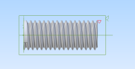
Bolt_007a.png

That is the 20mm * 2.5mm * 50mm bolt so far. The only thing, as you have mentioned, I cannot do so far is create the minor diameter because it is not known. Attempts on the way!
 

silver2row

Senior Member
Exacerbating the issue here...I have gotten only so far but it has proved valued. The only thing I have been unable to do is this:

1. Create the minor thread diameter with the given example. Not your issue. I understand. I will attempt it again and soon. I have some "eye candy" to view...

7a.jpg

It is really near perfect except for some cosmetic features that printing with an oversized nozzle will allow and achieve.

Seth

P.S. I think the reason I could not account for the minor thread diameter is that:

1. My References were not toggled to display.
2. My line where the major diameter from the top of the polygon to the center of the bolt shown was ________. I am without understanding again. Sorry.
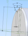
3. The reference line is just that...a reference. It is not an actual line in the equation/build. I think this may help you all help me more than me trying to explain with my limited vocabulary so far...

60_degrees_and_flying.png

The minor diameter is where the parallel line to the major diameter on the polygon is located. I just added the References to be toggled on. So, I will attempt again...
 

silver2row

Senior Member
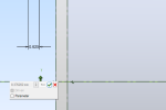
This may help more. The photo shows after picking dimension and trying to set the minor diameter...

I know something is missing. I will rewatch the video provided. Thank you all again.

dimension_to_minor_dia.png

See...I cannot change the dimension in length away or out of the 8.376202mm which it is at currently.

Seth
 

DavidJ

Administrator
Staff member
It might help if you post the file, so we can check out your profile sketch. From your screen grab I can't see what is fixing the minor diameter.

It looks like you've selected geometry to dimension which is already fixed by other dimensions/constraints.

The outline of your profile is coloured black, which indicates it is fully defined (unless you don't have degree of freedom colours enabled) - so you won't be able to change it by adding new dimensions, only by editing existing ones.
 

silver2row

Senior Member
Hmm...okay. Post the file? You mean, attach the file that I am altering?

Seth

P.S. In .stp or another form?
 

Attachments

  • Bolt_007ab.AD_PRT
    933 KB · Views: 3

Stu3d

Senior Member
I managed to open your part file but usually people create a package.
File menu - Package - Create.

You can't change the 8.376mm dimension because the distance of your sketch from the axis is already dimensioned at 10mm.
8.376mm is threrefore a driven dimension because it is controlled by the 10mm dimension.

Screenshot 2024-02-09 102241.png
 

silver2row

Senior Member
@Stu3d and @DavidJ ,

You guys got it. I will make a package next time and okay about the 10mm and 8.376mm being the lessor in this case. I just set the References toggled to on too late I guess.

Seth

P.S. Is there anything I can do or should I start from scratch? Learning new methods of interaction, i.e. my favorite... Oh, the package.
 

Attachments

  • Bolt_007ab.AD_PKG
    395.7 KB · Views: 0

DavidJ

Administrator
Staff member
Ah - couldn't see for looking!!

You've fixed the size of the flat across the bottom of the profile, the 60° angle, set the 2 sloping sides equal, and set the 10mm dimension to the top.

Suggest that you delete the 10mm dimension OR the 2.5mm dimension then dimension from axis to your 0.625 line.


For simple parts, posting the part itself is fine. package files make more sense when multiple linked files are needed (assemblies or drawings).
 

silver2row

Senior Member
@Stu3d and @DavidJ ,

Okay...so. When the size of the line arrives, I need not type "2" and "enter" to create the length of the horizontal line, i.e. my major diameter.

I will attempt without defining the length of the major diameter to start. And I got you so far, so. Either get rid of the 10mm major diameter since it may be false and/or the 2.5mm dimension...oh.

So, the 2.5mm is the equivalent of the parallel lines that are horizontal... Aw! I must have "accomplished" that by accident.

Seth

P.S. And yes sir, about that package and part difference. If it ever gets too complicated for one file, I will definitely use the package instead.
 

silver2row

Senior Member
Okay and My Plight,

Who knows what will transpire, right? I do not. So, in hindsight (at least for now), I should actually have a model of what exactly I am trying to convey. This would be a smarter way to go about trying to bother you guys/gals about random articles. Nevertheless, thank you for your kind welcoming and attentive assistance.

I erased the 10mm and put it back. So, I achieved nothing different. I am now learning how to do what the video stated from @HaroldL and his very slow-understood speech. By the way @HaroldL , I greatly appreciate you speaking slowly on your videos. Not a lot of banter nor odd noises from speaking too quickly. Thank you.

Seth

P.S. There is a way to put the radius of the bolt along with the minor diameter of the pitch or TPI. I am going through ideas now with the two videos and I will report back!
 

DavidJ

Administrator
Staff member
You don't have to type into the real time dimensioning boxes - you can type the dimension in at that stage, add it manually later using dimension tool, or rely solely on applying sketch constraints. It all depends on what you want to achieve.

Also try to bear in mind that there isn't single 'correct' way - there'll usually be at least 2 or 3 slightly different approaches, all of which can work. You may find that a particular approach is more comfortable than others for how your mind works.
 

HaroldL

Alibre Super User
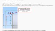
You have the profile dimensioned incorrectly - remove the 2.5 Pitch dimension then you will be able to dimension the Minor Radius.
-----------------

wrong dim for thread profile.jpg
 

silver2row

Senior Member
Thank you! I will attempt this idea and more this weekend. I am getting close to mfg. the part like the two videos describe.

Seth

P.S. I will not dimension the pitch of the major diameter. And right, yes sir. The major diameter is correct because I have a 20mm bolt with radius of 10mm. Sorry about changing the bolt structure midstream here. I just thought I would "play" with the different sizes to see what I could do.
 
Top