Good day,
I want to share some workarounds Ive come across and need some help on this. Worthy scan hardware are very expensive so there aint many options with this challenge. I finally found software to help to do what I wished GMD could do. GMDs latest version have a new tab called "Scanning and Mesh". Its been helpful but cant get satisfying results. The "surfacing" functions also helped a lot. In particular the stitch function. I will explain and add screenshots to make things clearer.
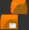
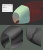
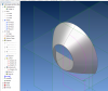
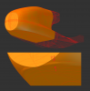
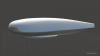
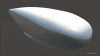
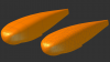
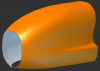
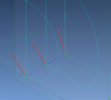
Ive had this challenge where I had to measure parts already made, to make CAD models of. Its quite big with spans of 33 feet/10m. Ive tried many ways but after all the advice I found I realised you just cant do it in single lofts. You need to do it in sections. We got a self leveling cross line lazer to help with the measurements. Im a guy who loves my square and lazer. By placing another lazer square to the vertical beam of the other lazer I got my sections which represents the planes on which the co ordinates fall. This post should give some perspective viewtopic.php?f=10&t=14439 As you will see over here, not only did I have trouble making accurate lofts but there were annoying errors that came with it. (INCONS_FACE: inconsistent face-body relationships/ Operation: Boss) And the main cause for this, I believe, were due to sketches falling on the exact same plane? The start of a new lofted sketch and the end of a previous one. (When a loft is done I use "project to sketch" to get the next sketch for the following loft.) Sometimes the lofts didnt give this error and other times it did. As mentioned, I placed another plane .1mm/0.004" away from the last one and pasted the copied & projected sketch, from the last loft, onto it. That way I dodged this error and kept everything in one file. Rather than making a copy of the file to boolean unite later. As you will see the last two screenshot were lofts made in the same tree. So I saved a copy of the file with the lofts which were problematic with the rest and joined them through boolean. Then an even bigger challenge stared me in the face. How will I get these parts hollow????? Thats when I realised the shell function only works 15% of the time I need it. Guess it doesnt "like" most organic shapes. I tried to overcome this by making another copy of the full boolean and scale it down for boolean subtract by about .98. When you do this the center of mass should be aligned to get perfect offset. Thus representing the skin. Its not an accurate or professional solution but it got me where I wanted to be. At the time.
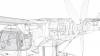
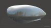
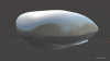
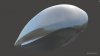
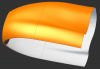
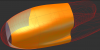
By now you might be thinking I am thinking this is not the best software for the job? Not what im thinking! I still believe this is where hand and machine meets. The following screenshots should speak for themselves. Problem now is where do I go from here. GMD doesnt seem to keep the smooth looking imported mesh when it is transformed by the "Convert Mesh to Solid" function? I dont know much about Geomagic Studio but I have a feeling this might fill in where GMD shorts??? Anyone who owns this and know how good it is? I wont be able to michine accurate parts with Alibre CAM if GMD doesnt handle the mesh properly. Theres an awful amount of accuracy lost in the mesh conversion. And I dont believe its another visual glitch. Will prove my point in screenshots.
I found software which gave me hope on the matter so I know it is possible! Only a matter of mesh handling by GMD now. I understand mesh software are more on the organic side of the cad world.
Any help appreciated. Always open for ideas.
Regards
Another post regarding the matter viewtopic.php?f=10&t=14577
I want to share some workarounds Ive come across and need some help on this. Worthy scan hardware are very expensive so there aint many options with this challenge. I finally found software to help to do what I wished GMD could do. GMDs latest version have a new tab called "Scanning and Mesh". Its been helpful but cant get satisfying results. The "surfacing" functions also helped a lot. In particular the stitch function. I will explain and add screenshots to make things clearer.
Ive had this challenge where I had to measure parts already made, to make CAD models of. Its quite big with spans of 33 feet/10m. Ive tried many ways but after all the advice I found I realised you just cant do it in single lofts. You need to do it in sections. We got a self leveling cross line lazer to help with the measurements. Im a guy who loves my square and lazer. By placing another lazer square to the vertical beam of the other lazer I got my sections which represents the planes on which the co ordinates fall. This post should give some perspective viewtopic.php?f=10&t=14439 As you will see over here, not only did I have trouble making accurate lofts but there were annoying errors that came with it. (INCONS_FACE: inconsistent face-body relationships/ Operation: Boss) And the main cause for this, I believe, were due to sketches falling on the exact same plane? The start of a new lofted sketch and the end of a previous one. (When a loft is done I use "project to sketch" to get the next sketch for the following loft.) Sometimes the lofts didnt give this error and other times it did. As mentioned, I placed another plane .1mm/0.004" away from the last one and pasted the copied & projected sketch, from the last loft, onto it. That way I dodged this error and kept everything in one file. Rather than making a copy of the file to boolean unite later. As you will see the last two screenshot were lofts made in the same tree. So I saved a copy of the file with the lofts which were problematic with the rest and joined them through boolean. Then an even bigger challenge stared me in the face. How will I get these parts hollow????? Thats when I realised the shell function only works 15% of the time I need it. Guess it doesnt "like" most organic shapes. I tried to overcome this by making another copy of the full boolean and scale it down for boolean subtract by about .98. When you do this the center of mass should be aligned to get perfect offset. Thus representing the skin. Its not an accurate or professional solution but it got me where I wanted to be. At the time.
By now you might be thinking I am thinking this is not the best software for the job? Not what im thinking! I still believe this is where hand and machine meets. The following screenshots should speak for themselves. Problem now is where do I go from here. GMD doesnt seem to keep the smooth looking imported mesh when it is transformed by the "Convert Mesh to Solid" function? I dont know much about Geomagic Studio but I have a feeling this might fill in where GMD shorts??? Anyone who owns this and know how good it is? I wont be able to michine accurate parts with Alibre CAM if GMD doesnt handle the mesh properly. Theres an awful amount of accuracy lost in the mesh conversion. And I dont believe its another visual glitch. Will prove my point in screenshots.
I found software which gave me hope on the matter so I know it is possible! Only a matter of mesh handling by GMD now. I understand mesh software are more on the organic side of the cad world.
Any help appreciated. Always open for ideas.
Regards
Another post regarding the matter viewtopic.php?f=10&t=14577


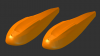

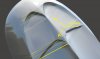
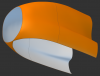

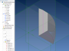
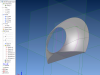
") Seems like my best bet would be to model the whole body in GMD and use MoI to give the body thickness. Theres one small problem with this way through MoI. The shell is made perpendicular to the selected face. But if the body is complete this wont be a problem when all the edges are 100% flush.
Seems like my best bet would be to model the whole body in GMD and use MoI to give the body thickness. Theres one small problem with this way through MoI. The shell is made perpendicular to the selected face. But if the body is complete this wont be a problem when all the edges are 100% flush.