I have been trying to put a .187 fillet on the edge of a part and have been unsuccessful.
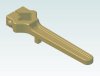
Here is a snapshot of the part, the blue line on the left side is where I have been to do the .187 fillet. I have been getting this error message. "BL_CAP_COMPLEX: could not find acceptable sequence of capping faces to trim blend face" I had trouble on the bottom of the other side and solved it by turning on variable radius. If i do the other side .1to .187 I can get some fillet on the left side but that isn't what I want.
Art


")