What's new

Trying to add a second revolve cut

Garryp4

Member
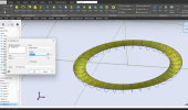
This is just an arbitrary drawing trying to learn this software. What I'm trying to do is make a second o-ring groove inside of the first one. I made a new plane for the revolve to rotate around but now can not seem to get the circle to trim to make the groove. I tried to add an axis but could not figure it out. The PDF manual I got today after purchasing Atom 3D does not explain it very well and I can not find a good example.

Any suggestions
 

Attachments

  • o-rings.AD_PRT
    335 KB · Views: 11

Ken226

Alibre Super User
So, i could be misunderstanding, but you are trying to make another groove like the existing one? Smaller in diameter, on the same face?

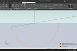
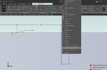
if so, activate a default plane, then use the right and left mouse buttons simultaneously to rotate the view a little. So you can see the existing groove. Use "project to sketch" command, and select "reference geometry-maintain association", the "ok", then click "reset view", to get you back to the default sketch view. This is so you can see the location of the existing groove geometry.

Like this:


After you click "reset view", you will be able to see reference figures that show where the existing groove is. The two dots on the left show the groove. Here, ill ad a circular reference figure, to better illustrate the location of the existing groove. Like this:


Now I can add a curcular Sketch figure, where I want the new groove to be:


Then, deactivate sketch. Revolve cut. Select the sketch and the Y axis:
 
Last edited:

albie0803

Alibre Super User
Reopen you original sketch (right click Sketch1 > Edit) and put the the circle in where you want it just like you did the first one.
 

Garryp4

Member
Thanks for both the replies. I first tried the method as Ken described but did not see the two dots that show where the groove is. Are the :


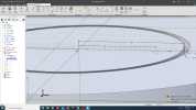
1668531262655.png

There are two green arrows. I don't see the same in the constraints options so don't know what they are. I still can not draw a circle on the sketch. I can draw a circle on the face which does not help with a second o-ring groove. I don't quite understand what the project to sketch does.
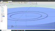
1668531421729.png


Next I tried what Albie suggested. I was able to get the circle drawn and trimmed.
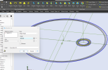
1668532123602.png

As soon as I deactivate the sketch I get the second groove as he also showed.

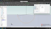
1668532377129.png

However, what I want to do is rotate the second o-ring groove around a different axis. I had added another plane hoping to use its axis but the new groove rotates on the same plane as the first groove. What I want to draw is ports sealed with o-rings anywhere on the face, not having a 'doughnut' shape. How can I do that?

And thanks for the help. This is all new to me. I did 2D Autocad back in the i386 days. All the cad I have done since is drawing circuit boards in 2D.
 

Ken226

Alibre Super User
Thanks for both the replies. I first tried the method as Ken described but did not see the two dots that show where the groove is. Are the :


View attachment 37791

There are two green arrows. I don't see the same in the constraints options so don't know what they are. I still can not draw a circle on the sketch. I can draw a circle on the face which does not help with a second o-ring groove. I don't quite understand what the project to sketch does.
View attachment 37792


Next I tried what Albie suggested. I was able to get the circle drawn and trimmed.
View attachment 37793

As soon as I deactivate the sketch I get the second groove as he also showed.

View attachment 37794

However, what I want to do is rotate the second o-ring groove around a different axis. I had added another plane hoping to use its axis but the new groove rotates on the same plane as the first groove. What I want to draw is ports sealed with o-rings anywhere on the face, not having a 'doughnut' shape. How can I do that?

And thanks for the help. This is all new to me. I did 2D Autocad back in the i386 days. All the cad I have done since is drawing circuit boards in 2D.

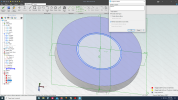
In your first post I missed the part where you wanted to revolve the second groove around a different axis.

Now I'm confused as to why your having any trouble at all. Your part file already has the sketch and the axis, and everything seems to work fine.

click "REVOLVE CUT", select sketch 3 as your "sketch to revolve" and axis 4. It worked fine for me..

1668535135045.png
 

Ken226

Alibre Super User
In this sketch (sketch #2) , your problem is that the sketch is an open loop, and there is an additional vertical line that is an open loop. Alibre doesn't like open loops.

1668535525253.png

This early in your Alibre learning experience, you should start using the "analyze sketch" tool religiously, it will inform you if there is a sketch problem.


Here, i fixed the sketch by adding one more line, across the top to close it.

1668535582732.png


now that it is closed, there is a vertical line to the right of the profile. You can't leave a sketch figure in an unclosed loop like that. Right click in, then convert it to a reference figure. Which you can use to insert an axis.

1668535765678.png


After that is done, you can use the axis to do a revolve cut of the closed figure.

1668535879628.png
 
Last edited:
Top