What's new

TUTORIAL: Creating a cavity split in Moi

bigseb

Alibre Super User
This thread refers.

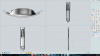
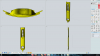
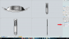
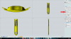
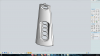
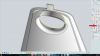
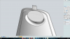
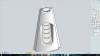
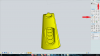
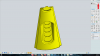
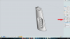
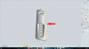
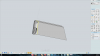
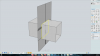
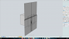
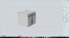
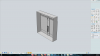
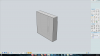
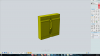
Tome asks how to create cavities for a mould from an imported step file using Moi. The following steps will explain the steps:
 

bigseb

Alibre Super User
STEP 1

Open Moi and import the model:


Clicking on the model will show that it is a solid:
 

Attachments

  • 01A.png
    01A.png
    383.7 KB · Views: 30
  • 01B.png
    01B.png
    319.4 KB · Views: 25

bigseb

Alibre Super User
STEP 2

I like to keep the original model available so I create a copy of it and work with the copy. below you will see the original:


... and the copy:
 

Attachments

  • 02A.png
    02A.png
    319.1 KB · Views: 19
  • 02B.png
    02B.png
    319.6 KB · Views: 21

bigseb

Alibre Super User
STEP 3

The next step is to separate the imported solid into surfaces. Click on the model and then click on separate:
 

Attachments

  • 03A.png
    03A.png
    358.1 KB · Views: 22

bigseb

Alibre Super User
STEP 4

Switch to 3D view. In this step all the unnecessary surfaces will be deleted i.e all the surfaces that will be needed for that particular cavity are to be kept. A bit of planning and forward thinking is required here as you are essentially creating the splitline. Simply select the surfaces you don't need and delete:
 

Attachments

  • 04A.png
    04A.png
    382.5 KB · Views: 15

bigseb

Alibre Super User
STEP 5

All the holes need to be closed. Do this by selecting the edges of a hole and creating a planar surface:
 

Attachments

  • 05A.png
    05A.png
    626.2 KB · Views: 16
  • 05B.png
    05B.png
    526.3 KB · Views: 12

bigseb

Alibre Super User
STEP 7

Join all the surfaces:
 

Attachments

  • 07A.png
    07A.png
    326.1 KB · Views: 15
  • 07B.png
    07B.png
    382.2 KB · Views: 9

bigseb

Alibre Super User
STEP 8

Time to extrude the edges to create the splitline surface. Click on Extrude:


Select the edges you want to extrude:


Within the extrude tool you specify the direction of the extrusion (should it not extrude in the correct direction). This is the result:
 

Attachments

  • 08A.png
    08A.png
    347.9 KB · Views: 13
  • 08B.png
    08B.png
    333.8 KB · Views: 18
  • 08C.png
    08C.png
    263.5 KB · Views: 13

bigseb

Alibre Super User
STEP 9

Repeat Step 8 for the remaining sides. When done join all the surfaces:
 

Attachments

  • 09A.png
    09A.png
    265.1 KB · Views: 11

bigseb

Alibre Super User
STEP 10

Switch to front view for the next step. Draw a line down the middle of your part (snaps will make this a doddle). Next select the rectangle tool (centre to edge) and pick the middle of the line you just created as the centre. In the rectangle tool you can enter the limits of your rectangle:


Switch back to 3D view. Extrude the rectangle in arbitrary distance in both directions. Delete the rectangle and line after this step:
 

Attachments

  • 10A.png
    10A.png
    227.5 KB · Views: 14
  • 10B.png
    10B.png
    213.1 KB · Views: 13
  • 10C.png
    10C.png
    294.1 KB · Views: 10

bigseb

Alibre Super User
STEP 11

Time to trim the edges. Click on the trimming tool. Select the surface you want to trim (box) and click done. Select the cutting surface and click done. Select the section of the box you don't want and click done:


Repeat process for the splitline surface:
 

Attachments

  • 11A.png
    11A.png
    278 KB · Views: 13
  • 11B.png
    11B.png
    250.7 KB · Views: 12

bigseb

Alibre Super User
STEP 12

Rotate the model to see the back. Trim the edges of the box to create the desired plate height:


Create a planar surface to close the back:
 

Attachments

  • 12A.png
    12A.png
    275.8 KB · Views: 12
  • 12B.png
    12B.png
    227.1 KB · Views: 9

bigseb

Alibre Super User
STEP 13

Last step. Select the entire model and click on join to create a solid which can then be imported into Geomagic Design:
 

Attachments

  • 13A.png
    13A.png
    260.2 KB · Views: 16

bigseb

Alibre Super User
Hopefully this was helpful. If anything is unclear please feel free to ask. Attached below is the model.
 

Attachments

  • Tutorial.3dm
    878.5 KB · Views: 16

bigseb

Alibre Super User
I just remembered another tutorial I wrote on using Moi to created cavity splits. This tutorial uses a different method due to the complexity if the article. Combined with this tutorial it shows the usefulness of Moi for such operations.

Find it here

:)
 
Top