You are using an out of date browser. It may not display this or other websites correctly.
You should upgrade or use an alternative browser.
You should upgrade or use an alternative browser.
TUTORIAL: Single Speed Gearbox with Python Scripting
- Thread starter ajayre
- Start date
Looks potentially interesting - I had looked at your site, but am still not really clear about quite what your ADScript thing offers. Some more detail on what capabilities it has (or might have in future) would be helpful. Basically what does it do, how do I use it?
I've recently had requests for a gear generation tool, but the requestor also wanted to be able to adjust addendum and dedendum - there is potential for tools which either give add on functionality or make it easier to create such functionality (I'm not sure which category your ADScript falls into).
I've recently had requests for a gear generation tool, but the requestor also wanted to be able to adjust addendum and dedendum - there is potential for tools which either give add on functionality or make it easier to create such functionality (I'm not sure which category your ADScript falls into).
ajayre
Alibre Super User
It falls into both categories. For example it provides add-on functionality through it's built-in gear module but it also makes it easier for you to write your own custom gear module in Python.
Current built-in functionality off the top of my head:
- create parts, points, axes, planes
- create sketches
- supports lines, polylines, arcs, circles, bsplines and reference items in sketches
- extrude boss/cut
- revolve boss/cut
- sweep boss/cut
- fillet with constant and variable radii
- chamfer
- save as Alibre file or STL
- open existing file
- close file
- set material density and read out mass
- involute gear generation
The complete Python standard library is available which provides a lot of functionality such as mathematical functions, file access, network access, etc. http://docs.python.org/2/library/
ADScript itself provides a script editor and also a Python console which allows you to enter individual pieces of code and immediately see the result. It also allows you to write scripts that prompt the user for input and then use that input. For example you might create a gearbox script that when run asks the user for the starting parameters instead of putting them directly into the script.
Polyline support includes finding the intersection of two polylines, trimming, merging, copying, etc.
In theory it should be easy to write new 2D file importers, create sketches that are reused over and over again among a set of parts, STL export post-processors, etc.
For the future I intend to add support for the remaining functionality in the API but also write more built-in modules along the lines of the gear generator.
Andy
Andy - thanks for the extra information, but it's falling into the category of help written by the programmer. It may be obvious to you, but coming to it cold I've still little idea about this. What you originally posted was not a 'tutorial' as I understand it.
Sorry to sound negative - this might be very helpful/exciting (I just don't know). Anything that makes API more accessible is to be applauded, but I'm still baffled. No idea how to access it, no idea what rules exist for the gear generator. Please treat us more like idiots and explain a bit more...
Sorry to sound negative - this might be very helpful/exciting (I just don't know). Anything that makes API more accessible is to be applauded, but I'm still baffled. No idea how to access it, no idea what rules exist for the gear generator. Please treat us more like idiots and explain a bit more...
ajayre
Alibre Super User
I haven't released it yet so there isn't a way to access it.
The gear generator uses four parameters:
- pressure angle
- pitch diameter
- diametral pitch
- number of teeth
All but the pressure angle are linked by a simple equation so all you need is the pressure angle and any two of the other parameters.
Looking at the code the addendum and dedendum are defined as:
addendum = 1 / P
dedendum = 1.157 / P
where P is the diametral pitch. I'm not sure what effect varing those formulas would have. What was the requirement you received?
Andy
Like many customer requests it was vague - just the need to vary addendum and dedendum. I can try to get more definite information. Have never had similar request before, but this user insists it is critical to their business...
Can the Gear generator also cope with Module gears?
Maybe I should have asked 'how would I access it ?' (if it were released).
Can the Gear generator also cope with Module gears?
Maybe I should have asked 'how would I access it ?' (if it were released).
")
This product might also be of interest:
http://gearotic.com/
Gearotic is aimed at the hobbyist, but might have the features you need. There is a free demo and some tutorials on YouTube so you could check it out before paying the $120 price tag. I have a copy but haven't tried to use it yet.
Mike
http://gearotic.com/
Gearotic is aimed at the hobbyist, but might have the features you need. There is a free demo and some tutorials on YouTube so you could check it out before paying the $120 price tag. I have a copy but haven't tried to use it yet.
Mike
ajayre said:I haven't released it yet so there isn't a way to access it.
The gear generator uses four parameters:
- pressure angle
- pitch diameter
- diametral pitch
- number of teeth
All but the pressure angle are linked by a simple equation so all you need is the pressure angle and any two of the other parameters.
Looking at the code the addendum and dedendum are defined as:
addendum = 1 / P
dedendum = 1.157 / P
where P is the diametral pitch. I'm not sure what effect varing those formulas would have. What was the requirement you received?
Andy
What about minor and major diameter change on construction? How about measure over pins? Are those things that are possible to include in something like this? How about precision? Involutes with higher accuracy will have more tangent circles in order to keep the accuracy level than one with less accuracy. Sorry but I use to have the top of the line program for involute gear generation on our wire edm and have never found anything better. The program stopped working and I must upgrade to a new version in order to fix our problem but it was very costly as it is an entire cad/cam package. Anyhow it would be very useful if I could generate precision involute once again (we use to do gauges for customers and now I have trouble getting a precise gear least ways a gauge). Doing involute gears is like doing an ellipse. Many people (not in cad or engineering work) think an ellipse is simple an oval or oblong not a calculated form.
Hopefully the basic routines that generate the involute could be tweaked to produce involute splines (male & female) for power transmission without huge difficulty - there seem to be several ANSI/DIN standards that are widely used - most of the tools I've come across export a DXF of the complete profile, which ends up being very slow in Alibre/Geomagic (which works much better starting from a single tooth then patterning the feature).
Yes I agree by doing a single tooth it will be much better. That is also the way our other software worked as well. Easier to make changes that way when all you need to do is adjust the one tooth and not have all the other things linked in the sketch. I have a 2 inch thick gear book with just about everything a person could need in gears but for spur gears and basic involutes it is easy. Just when doing gauges it requires tweaks to the basics and then there are the non-standard forms like we dealt with. Basically automotive drive splines and they were the pickiest bunch out there. We make spline broaches for them as well and if we were to get a new form right now we would be stuck.
ajayre
Alibre Super User
OK, to answer some questions raised:
The module = 1 / diametral pitch.
The software runs as a standalone application and detects when Geomagic Design is running automatically. There is a script editor where you can create your script then you click on the run button to try it out.
I'm not sure about minor and major diameter change and measure over pins - I would have to research that.
For each involute curve 20 points are calculated. Then a third order bspline is generated through those points. It would be trivial to increase the number of points used. Is 20 not enough?
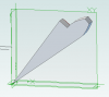
ADScript already contains the ability to generate a single tooth and here is an example:
this can then be patterned in 2D, however perhaps it is better to create something like this and pattern it in 3D? I don't know...
Andy
The module = 1 / diametral pitch.
The software runs as a standalone application and detects when Geomagic Design is running automatically. There is a script editor where you can create your script then you click on the run button to try it out.
I'm not sure about minor and major diameter change and measure over pins - I would have to research that.
For each involute curve 20 points are calculated. Then a third order bspline is generated through those points. It would be trivial to increase the number of points used. Is 20 not enough?
ADScript already contains the ability to generate a single tooth and here is an example:
this can then be patterned in 2D, however perhaps it is better to create something like this and pattern it in 3D? I don't know...
Andy
Attachments

Lew_Merrick
Guest
Andy,
Yes, it is a crass comment, but you have left off the fillet radius at the root of the tooth. That is important in gear quite often...
Yes, it is a crass comment, but you have left off the fillet radius at the root of the tooth. That is important in gear quite often...
ajayre
Alibre Super User
Lew_Merrick said:Andy,
Yes, it is a crass comment, but you have left off the fillet radius at the root of the tooth. That is important in gear quite often...
Also undercutting is sometimes required. The aim of being able to generate a single tooth is so you can tweak it to your requirements and then pattern it. The gear generator has created the involute curve for you which is the most difficult part.
Andy
albie0803
Alibre Super User
ajayre said:OK, to answer some questions raised:
The module = 1 / diametral pitch.
Andy
Correction: Module = 25.4/ DP and DP = 25.4/Module
You know your DP. Anyhow the number of points required is really more of a desire to stay within a given tolerance. As you know the form of the tooth is a calculation at every point and then you are connecting as you say with a b-spline. The software we had actually connected using tangent radii. Using the radii made it more simple to actually modify the form but still no more easy to see a true deviation. 20 points probably is very good but without some testing it would be hard to say for sure. Sounds like you have a very good way of doing the geometry so my bet is the only issue with tolerance would be based on size of tooth. A very large tooth may require more points to stay within a given tolerance. The gauges I had to do for instance had a .0002 over pin tolerance and a .0001 form tolerance (inches). Very tight for an involute gear over the diameter. It was so tight that our machine could only make a good gauge about 50% of the time according to the independent inspection company.
As for the variance from the form normal there is where I would have problems. Most of the time for instance I had to change minor and major diameters along with diameter over pins in order to make a gauge based on the tolerance range provided. Some times they specified tooth width or even a diameter over two sizes of pins to insure their tooth form accuracy. Very touchy stuff but like I said the software was great. Even had to show their engineers the software we used as they could not understand the difficulties their tolerances made. (like .0002" over pins was suppose to be easy to hold) They could not understand that the tolerance over pins was much larger than the form deviation without actually seeing it in cad. The trouble with the b-spline is in checking of these by using tangent circles. It is easy to do when using tangent circles but we could never get the software to place a tangent circle to a b-spline in those days.
As for the variance from the form normal there is where I would have problems. Most of the time for instance I had to change minor and major diameters along with diameter over pins in order to make a gauge based on the tolerance range provided. Some times they specified tooth width or even a diameter over two sizes of pins to insure their tooth form accuracy. Very touchy stuff but like I said the software was great. Even had to show their engineers the software we used as they could not understand the difficulties their tolerances made. (like .0002" over pins was suppose to be easy to hold) They could not understand that the tolerance over pins was much larger than the form deviation without actually seeing it in cad. The trouble with the b-spline is in checking of these by using tangent circles. It is easy to do when using tangent circles but we could never get the software to place a tangent circle to a b-spline in those days.
Lew_Merrick
Guest
Andy -- Diametral Pitch is, by definition, an inch-based measurement.ajayre said:In the tutorial I only used millimeters so 25.4 is not required, right? I.e. it depends on the units of the diametral pitch?