What's new

TUTORIAL: Single Speed Gearbox with Python Scripting

ajayre

Alibre Super User
Go to Start -> All Programs -> WizoScript -> Reference Manual.

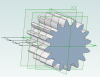
Thanks for the suggestion regarding tooth cut outs. This is something I will look at working on. Do you have a source for the descriptions of the three sketches in terms of shape/size/position etc?

I have Geomagic Design Elements so I don't have Vault to test with, sorry. :( I assume saving from within Geomagic Design works fine, so I am unsure why saving via WizoScript would not work - they should do the same thing.

Andy
 

Frank

Senior Member
Andy,
Do the commands used in the manual represent a complete list of all
the Alibre/Gm commands available via wizoscript for Python?
What is the original source of these commands-i.e. Alibre,Python,Wizoscript(you),other open source?
BTW,Wizoscript opens ok in Alibre 14.0.4.14056.
Many thanks for this - great work.
Regards
FrankG
 

ajayre

Alibre Super User
Hi Frank,

The reference manual contains a complete description of everything that is supported.

WizoScript exposes what 3DS provides in the Geomagic API, but adds additional original functionality such as sketch manipulation, gears, polylines, etc.

Andy
 

albie0803

Alibre Super User
ajayre said:
.....Do you have a source for the descriptions of the three sketches in terms of shape/size/position etc?
Andy

Umm....not sure what you are asking here. If I understand correctly, the cutout shape I use is just a rough drawn spline of a tooth flank and root mirrored and then joined with a curve at the top. I work at a gear shop and all my drawn teeth are only eye candy as we have the proper gear cutting machines.

OK....I've done some more thinking....(a dangerous thing I know)
If I name sketches and planes correctly, I should be able to set my front plane and tooth shape and then use wiso to create the middle and back planes and copy and rotate the tooth sketch onto those planes and then loft cut then pattern
 

ajayre

Alibre Super User
Yes, that should be possible. Please post your example file and I will see if I can create an example script.

Andy
 

albie0803

Alibre Super User
Ok, back from the holiday season and still very interested in this topic

Here is the test part and associated script. It successfully copies my existing sketch but I can't find a loft cut command to create the tooth.

Code:
MyPart = Part("New Gear", False)
XYPlane = MyPart.GetPlane("XY-Plane")
MySketch = MyPart.GetSketch("ToothTop")
MidPlane = MyPart.AddPlane("Mid Plane", XYPlane, -50)
NewSketch = MyPart.AddSketch("mid", MyPart.GetPlane("Mid Plane"))
NewSketch.CopyFrom(MySketch, 10, 0, 0, 0, 0, 0, 0, 100.0)
BasePlane = MyPart.AddPlane("Base Plane", XYPlane, -100)
NewSketch = MyPart.AddSketch("base", MyPart.GetPlane("Base Plane"))
NewSketch.CopyFrom(MySketch, 20, 0, 0, 0, 0, 0, 0, 100.0)


How do you use the Read() command to prompt for input? I tried

toothlength = Read()
MidPlane = MyPart.AddPlane("Mid Plane", XYPlane, -toothlength/2)
 

Attachments

  • New Gear.AD_PRT
    288 KB · Views: 21

ajayre

Alibre Super User
albie0803 said:
It successfully copies my existing sketch but I can't find a loft cut command to create the tooth.

Lofting is not supported in the API in Geomagic. Hopefully it will be in the next Geomagic release.

albie0803 said:
How do you use the Read() command to prompt for input? I tried

toothlength = Read()
MidPlane = MyPart.AddPlane("Mid Plane", XYPlane, -toothlength/2)

The Read function always returns a string, so you will have to convert the input to a float. Try this:

Code:
MidPlane = MyPart.AddPlane("Mid Plane", XYPlane, -float(toothlength)/2)

http://stackoverflow.com/questions/379906/parse-string-to-float-or-int

Andy
 

albie0803

Alibre Super User
albie0803 said:
Addendum diameter change ability is very important as often gears are tweaked up and down to get a desired centre distance rather than the proper centre distance for the gear set. Also, we often oversize the large gear and undersize the pinion gear so that later the large gear can be "tickled up", normally by grinding the teeth back, and then a new pinion gear can be made, this time on size.

I would like to suggest that this be addressed by adding an optional parameter to the gear function that specifies the OD to be used when the tooth is generated in place of the calculated one. Assuming of course that this can be done :D

GearSketch = MyPart.AddGearDN("Top", 3.5, 25, 20, 0, 0, MyPart.GetPlane("XY-Plane"), 7.750)

Current generated OD would be 7.714 (inches) DP is an inch based system after all.

Or equivalent metric size depending units being used
 

JordanCClark

Alibre Super User
Sorry for the small hijack.

Andy, WizoScript has got to be one of the coolest things I've seen in a while. API functionality with the ease of Python! Now that I'm back current with my Alibre-- ahem... Geomagic toys... sorry-- It's about time for me to revisit Screw Selector.

Thanks for revitalizing things for us!
 

ajayre

Alibre Super User
albie0803 said:
Addendum diameter change ability is very important as often gears are tweaked up and down to get a desired centre distance rather than the proper centre distance for the gear set. Also, we often oversize the large gear and undersize the pinion gear so that later the large gear can be "tickled up", normally by grinding the teeth back, and then a new pinion gear can be made, this time on size.

Does the attached file demonstrate what you mean? It has three gears stacked, each one a slightly different size based on tweaking the addendum and dedendum. Notice how the "top land" for the teeth decreases. This tells me that there is a limit to how far the gear sizes can be tweaked. So is this what you expected?

I used the following formulas:

Code:
Addendum = a / DiametralPitch
Dedendum = d / DiametralPitch

Andy
 

Attachments

  • SpurTest.AD_PRT
    1.8 MB · Views: 10
  • spurtest.png
    spurtest.png
    34.2 KB · Views: 11

albie0803

Alibre Super User
Andy,

That is the sort of thing I am after. A lot is going to depend on what sort of accuracy you want in your program. For me, teeth on gears are just eye candy, as long as the shape is about right and they easily show if they are a left or right helical or a straight spur gear, that is all I need. For me, the important thing is the right OD so that the blank is turned correctly. I start with a blank and then add a configuration that has a gear tooth cutout and then a circular pattern. My main drawing is of the blank (for turning) with the teeth shown in an isometric view.


In cutting oversize gears, lets say a standard gear is 100mm od and the cutter depth is 6mm from the od. If we oversize the gear to 102 the cutter depth remains at 6mm, it doesn't change to 7. So if the the addendum increases then the dedendum decreases and vis-versa. You are right in that there is a limit as to how much a gear can be changed.

Hmmmm......... Having thought about this while typing I have come to the conclusion that my preferred method of using this sort of function would be to create a blank first and then use the gear function to create a shape with a slightly larger od and then draw an outer circle and then use that created sketch to do an extrude cut to form the teeth. I am out to generate drawings where you are out to generate gear models. The accuracy you want for your models is going to determine how you actually program this.

I hope this rambling helps a bit. :D
 

Attachments

  • Capture.JPG
    Capture.JPG
    35.8 KB · Views: 49

Knickstab

Member
Hi Andy,

this is the easiest way to Programm Geomagic Design....

One Question : Is it possible to work with Assemblies ?
 

ajayre

Alibre Super User
Not yet. What kinds of problems do you see creating assemblies through scripts solve?

Andy
 

Knickstab

Member
Not very much:
As a beginning, the points would be enough 1-4.
1. insertion of parts / assemblies
2. Alignment of parts / assemblies to (named) Reference Planes, Lines, Points
3. Move Rotate / twisting of parts / assemblies
4. Anchor (fixing) of parts / assemblies
5. Pattern of parts / assemblies
6. Deleting parts / assemblies
It would be better with the points 5 and 6

For parts only one function is missing:
Boolean Subtraction
With this function you can draw 3D reinforcement in the concrete body ...
For me, as a structural engineer, this means I can use my HomeCad at work.
One Cad program and not three. A dream come true .... :mrgreen:
 

RocketNut

Alibre Super User
I have used Andy's gear generator and found it extremely easy to use. Just plug in the specs of the gear an just a few seconds the gear are drawn up. What I like is no matter how complex or the number of gears need in the drive train Wizo can handle it.

Its works great. :D

RocketNut
 

RocketNut

Alibre Super User
I forgot to mention that you don't have to be a programer or code righter. Just enter the gear function with the required info. The gear will be drawn up an ready to be used.
 
Top