What's new

Understanding simple equations between parts in assemblies

Hi Guys

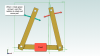
Kindly see attached image, part and assembly.

I can’t get my head around understanding simple equations between parts in assemblies.

I want the angle of the left and right part be the same with respect to the bottom, grounded part in this assembly.

So if I move any of the left or right part then the other will move as well.

How do I go about that?


Best regards,

Christian
 

Attachments

  • New Assembly (1).AD_ASM
    224 KB · Views: 3
  • Test.AD_PRT
    278.5 KB · Views: 5
  • 2020-11-27_13-30-21.png
    2020-11-27_13-30-21.png
    55.4 KB · Views: 20

HaroldL

Alibre Super User
Christian, It all starts at the part level. Make sure you design your parts with fully constrained sketches. IF you want a part to be symmetrical then make the sketch symmetrical about the default planes. Then in the assembly constrain the base part to the default planes and origin.

I would recommend that you do as Keith did and go thru the Alibre Exercise Manual, It will guide you through the steps to build parts and assemblies.

Finally, when you need to upload an assembly to the forum do so with a Package file (File>Package>Create) then all parts for the assembly are in one file.

I have edited your test part and the assembly to give(show) the final result you asked for. Once everything was constrained I used a Gear constraint on the arms with a 1:1 ratio. Drag one of the moveable arms and you will see the other follow.
 

Attachments

  • New Assembly-Constrained.AD_PKG
    41.1 KB · Views: 2
Last edited:
Thanks Harold.
This was just a quick and dirty example
(I have worked with Alibre since 2014)

I kan make it work with hidden links between left and right part, so that when I move one of the parts with my mouse arrow, then the other part moves equally.

I like the same function using equations between parts in assemblies. so that the other part is mooved too when I moove the first part with the mouse, not only by typing.

Is that possible in Alibre Atom?
 
Hello Christian To be clear, I know microscopically more than nothing about Atom 3D. However assuming that Equation Editor values act roughly the same and that "Variable Constraints" exist, it should be possible to "tie" the rotation of Parts together. This is a statement made in overall ignorance of Atom 3D. -- Lew
 

OrjanB

Senior Member
Hi Christian,

As far as I understand you want to make a mirroring movement.

I had the same problem and therefore developed a simple method for this using constraints and planes. I have Alibre Expert, but the tools needed are also available in Alibre Atom.

Due to lack of computer with Alibre (at the moment) I have not tested, but I assume you can adapt it to your need.

In my case I constrained planes to edges in order obtain dynamic linear movement.
In your case you can constrain planes to the moving edges and the fixed axis in the hinge for dynamic pivoting movement.

Link to my proposal:

https://www.alibreforum.com/forum/index.php?threads/mirror-constraint-in-assembly.21834/

Regards
Orjan
 

HaroldL

Alibre Super User
Orjan, Neat tip - Your method takes a bit more set up but I think is more accurate in terms of symmetric motion about the central plane than my example of using the Gear constraint. By adding a Angle Limit constraint the assembly the motion of both links mimics the gear constraint without having to first establish a equal starting angle for the links since that is automagically established by the crossing planes.
 
Hi All
Thanks a LOT for all your help.

Now I know, that it is a limitation in Atom, so instead I made a simple "connector" part that just consists of 2 very small rigids with a long distance between them and use that part to act as an invisible joint that connects 2 rotational parts together. Connectes above the axis on one part and below axis on other part.
It works for me as my rotation is only +- 45 degrees and the distance is relative long apart.
 
Top