What's new

updating of dimensions attached to nodes?

Cameraman

Senior Member
updating of dimensions attached to nodes?

I must be doing something wrong . . .

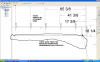
I created a part, then created a drawing and dimensioned it. Later, I went back and changed the part, and the new part is shown correctly in the drawing, but many of the dimensions were not changed, The dimensions in question appear to be attached to nodes, not the actual part geometry -- when the geometry changed, the nodes stayed where they were and the dimensions stayed with the nodes.

Is there a way to get the nodes to move where they belong?

For reference, I added most of my own dimensions because I was quite dissatisfied with the automatic ones placed by AD. For example, there are a number of dimensions to the ends of center marks -- the center marks moved, but the dimensions didn't. I was able to place dimensions this way with Inventor so I just sort of assumed that it would work in AD as well (there I go, assuming again).

Thanks in advance for your tips . . . if I don't see a way to recover, then I will just delete all of the affected dimensions and re-insert them <heavy sigh>.

Regards,
Greg :D
 

jwknecht

Alibre Super User


Check to make sure you are updating the drawing when you open it. In the tutorial (hit the Tutorials Tab on your Alibre home window) for 2D detailed drawing there is a section where it explains how to do this after changes are made to the part. I recommend doing the whole tutorial, it shouldn't take long and will get you up to speed.
 

Cameraman

Senior Member


Thanks for the response, John,

When I first got AD, the first thing I did was go through 3 tutorials: creating a part, sheet metal, and creating a drawing . . . I also went through a couple of sessions on the training CD's . . . so I was ready for the update dialog box when it came up and I think I did that part correctly. However, some of the dimensions updated and some did not. That's what makes me think that perhaps I was not using the intended procedure for applying dimensions.

Based on a quick troubleshooting analysis, it appears that the dimensions that failed to update were ones that I placed (all called "reference" dimensions by AD), and were typically dimensioned to "imaginary" points on the part (e.g., end of a center mark line, filleted intersection point of two lines, etc.).

I guess I should get some advice from the assistant before I go through and re-dimension the drawing to make sure that I do it correctly this time. I will also review the training CD lesson on dimensioning.

Regards,
Greg :D
 

ghislain

Member


I have the same problem.
Working with sheet metals,
making holes in it: positioning of holes relative to borderlines of flanges.
Make drawing, inserting centers, dimensioning using the middelpoints of the centermarks.
Update sheet metal part: changing de dimensions of the flanges, the positioning of the holes remains the same, relative to the borders (who changes from position). Save

reopen drawing:
in the drawing the form of the sheet metal and the position of the holes has changed as expected.
but: some points remain from the previous location of the center marks, 5 points for each hole. dimensions are attached to these old points, so now give the wrong measures. The centermark moved along whith the hole, OK; why does AD not cleaunup the centermark-points and relocates the dimensions???
I have to delete the wrong dimensions and remake them.
It' not possible to clean up the remaining points: you can select them (they changes their color) but can't delete.
This hapens sometimes. Mostly everything is OK.
I always have to check my drawing-dimensions after changing the sheet metal. Boring.
 

moyesboy

Alibre Super User


That really is not good. Have you reported this as an incident?
Maybe this will be sorted in the many drawing enhancements pomised "soon".
Presume you could dimension your hole to the physical hole before adding the centremarks - if you can discipline yourself to always do that!
 

lcguias

Member


Hi,

This is what I found.

In drawings you have 2 options. To "import" dim from 3D and to add dim in 2D.
Most of the time the dim created in 2D do not uptate, but the dim "imported" are updated.

Dan
 

siggy

Senior Member


I've done hundreds of 2D drawing views in Alibre and rarely have a problem with dims updating. If I choose line endpoints or nodes instead of the line itself when dimensioning I sometimes get this failure to update problem. However, I make a conscious effort to ensure I always dimension line to line and when I do the dims update as they should. Might want to give that a try.

Robert
 

swertel

Alibre Super User


A good rule of thumb is to make your models and drawings as you would with real material.

In terms of drawings, if your were to take a calipers and measure the distance that you are dimensioning, you would be from a surface to surface. Surfaces correlate to lines on drawings, not points.

Of course, there are instances in drawings where no line exists. Obviously you have to take a point. Let's just hope you don't have to inspect or gage to it.
 

NateLiquidGravity

Alibre Super User
I don't like to wake sleeping giants, but I'm having this problem on quite a few drawings of assemblies. 19 out of 46 dimensions are not updating to the part. That is over 40%. And that is only one of the many affected sheets. They are clinging to nodes floating in the middle of nowhere. On my drawings it appears to only affect dimensions that were done in a baseline fashion. I know I selected the face edges of the parts to dimension. I tried deleting the dimensions and reinserting them. Same thing happened to them after changing the parts/assembly.

This is not acceptable in a so called "Software for professional mechanical design, engineering and manufacturing applications."
 

Attachments

  • UNUPDATED NODES.PNG
    UNUPDATED NODES.PNG
    100.1 KB · Views: 162

NateLiquidGravity

Alibre Super User
:!: This is definately a bug of some type. :!:
If I edit the part so that the dimensions are not exactly the same degree orientation (horizontal originally), then they update. But if after that I set them back to exactly horizontal then they don't update any more. :evil:
 

mrehmus

Senior Member
I reported this problem to Support and got the reply they could not see the problem in the file I uploaded. It still happens though. And to make matters worse, if you add nodes in a 2D sketch, they will disappear when you attempt to print the page. The dimension made to the node will be there but the node is gone. It will reappear when you go back to the Sketch mode.

Why does Support act like everything one reports is new to them?
 

OTE_TheMissile

Alibre Super User
@Nate - I get that a lot too, and in general it's not uncommon for Nodes in a sketch that were a part of some curved geometry that was later removed to not only stick around but become impossible to delete.

For example, I'll put a tubing notch in the end of a plate and constrain the arc center to an axis, but then later on it turns out we're not going to weld it to round tubing, so I'll remove the notch and replace it with a straight line. But the Node that was the center point for the notch is still there, serving as the endpoint of a reference line that's colinear with the axis. Only now that the notch is gone, there's nothing to keep that Node from sliding up and down along the axis. What it does is create an extra DoF, so I'll finish the sketch but the DoF indicator won't read 0 and I'll be looking all over the place trying to find out what I forgot to dimension or constrain.

Also, has anyone else ever constrained a manually placed Node to the midpoint of a line and Analyze Sketch threw an Intersection issue?
 

NateLiquidGravity

Alibre Super User
Ok, support worked with me and saw the issue, the steps it can be reproduced with in my parts, and the long workaround that I'm forced to use for now. I think it will be escalated to development.
 
Top