What's new

Using Alibre to design a slot car track

iwanttoslot

Member
Hello

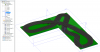
I am trying to design a slot car track in CAD to send to a company to rout a Slot car track. I use Alibre at work so I thought I would give it a go for this project. I am a little stuck on how to do this or even if it is the right package.
If a track is designable in Alibre I will give more information.

I would like to have an overpass.
I would like to avoid constant radius corners.
It has four lanes with 100mm spacing.
external gutter of 150mm.
internal gutter of 60mm
On three boards 3.0 x 1.8 meter

looks something like this
 

Attachments

  • IMG.jpg
    428.7 KB · Views: 134

Ralf

Alibre Super User
Hello iwanttoslot,

A track is designable in Alibre, and of course much more. :wink:
In order to help, it would be great, if you can give us more informations/dimensions about the "Road Layout".

Here is a rough model preview from your "hand sketch":
.
 

Attachments

  • Slot-Car-Trck-1.png
    Slot-Car-Trck-1.png
    76.1 KB · Views: 116

iwanttoslot

Member
i knew it would be possible. My experience is with engineering and machined parts so I find it hard to know where to start with some thing like this.
if you could give me some pointers I would appreciate that.
 

neilr

Senior Member
It actually sounds like it would be not that difficult to do. Once you have the proper profile for the track a simple sweep would give you the base part, I would then make as separate parts the ends that connect each length of track. After all there are only going to be so many lengths of straight sections and a few varieties of corners, then you would have to design each specialty piece, for the overpass-ramps, cross overs and such. After you are done making the parts you can then design as many track layouts as you want, each in it's own assembly. This is the way I approached a hobby project I am working on now, a modular castle....
 

Attachments

  • Twinforkscastle.jpg
    Twinforkscastle.jpg
    163.9 KB · Views: 94

bigseb

Alibre Super User
neilr said:
This is the way I approached a hobby project I am working on now, a modular castle....

Really Neil? Windows in a defensive structure? :roll:

Just kidding... looks great!! :D
 

neilr

Senior Member
Well thanks for the positive feedback, but if you took the same amount of time it took to write the post and looked you would have noticed that those are not windows , but arrow loops....And in truth many walled fortifications had windows, mostly in the towers and on the higher levels....

It is true in this pic it may not be that easy to see, but after I get it rendered they will stand out as arrow loops....
 

RCH_Projects

Alibre Super User
Easy mistake to make without historical reference.

But from a modern standpoint windows wouldn't matter as much as radar, anti-aircraft, etc. :mrgreen: .

(Bond, James Bond.)

(Looks great!)
 

neilr

Senior Member
Well after I get it rendered maybe I will do an animation with the towers opening up to expose the ICBMs hidden within :)
 

iwanttoslot

Member
I have made a 3d spline that roughly represents one edge of the track base.
Made a new plane on the end of the spline.
drawn the profile of the track bed.
Swept the track bed around the 3d spline.
I only get something if I tick the rigid box.

Doing something wrong.
Could someone please show me the errors of my ways
 

Attachments

  • shirley room 2.AD_PRT
    302 KB · Views: 15

RCH_Projects

Alibre Super User
I couldn't get yours to work, but I whipped out a test ok.


If I check the status of the 3D sketch I get "Sketch entity no longer available:com.alibre.design.ops.OperationTargetProxy original instanceof INameHolder = Sketch<1>"

In the 3D sketch I placed measurements from the spline origin to X Y Z planes and named them in the Equation editor.
Then I copied the values to create a "Point" and dragged it up the feature list so I can use "Coincident constraint" in sketch mode for exact alignment of sketches.


The 2d sketch has a lot of un-constrained lines - but no matter.


Maybe start again in a new part - don't delete references used to create the spline.

Thats all I see.
 

Attachments

  • Back to you.AD_PRT
    355.5 KB · Views: 13
  • xyz.jpg
    xyz.jpg
    201.4 KB · Views: 29
  • shirley room 2 (1).AD_PRT
    323 KB · Views: 10

RCH_Projects

Alibre Super User
Just to back up a little.

I suggest that you start by defining "Points" with XYZ instead of nodes.
It just makes everything easier and more formal.

At some point you will need to adjust the spline just because one lane may be longer than another (unless you want that :wink: ).

It's a lot easier to edit a point than a sketch.

Overall I think I would use the "Loft Boss" so you can include banking and such.
I'll try to post up an example.
 

RCH_Projects

Alibre Super User
A partial one lane track (I have to have a jump).

As you define more points/sketches the "Guide curve" is followed more closely.
You can measure and compare the (slot) curve edges to even up (average the two curves edges per slot I guess).

Generally after making the first track cross-section sketch, I copied it and added planes on the points to paste onto.
Without the points to use coincident constraint on those sketches it would be tough not to have the loft fail.

The sequence of creating and selecting Sketches can fail a Loft.
Experience tells.

If you care you can edit the loft I have and skip some sketches, then add your own for practice and to learn behavior.
In the Equation editor the "Slope" distance effects the corner angle.
I went back and modified Sketch 1 to illustrate the ability to modify the shape.


EDIT (attachment=0]WIP.AD_PRT[/attachment) - VERSION ERROR

Maybe this will work for some effort.
 

Attachments

  • jump.jpg
    jump.jpg
    229.1 KB · Views: 30

RCH_Projects

Alibre Super User
Reviewing; the guide curve are not required.

For a little exercise I'll put together a highly dynamically modifiable track and post it up.
 

neilr

Senior Member
OK had a chance to go over some of the stuff here. Well 1st thing I noticed is the the narrow stretch is to close together and the trck will intersect itself there so I moved them apart to more than 1000mm . Next the first turn is an inside turn and the track profile cannot make that turn without again self intersecting so I made that turn a bit wider...not wide enough in my first attempt but I removed half of the track profile and it swept the 3D spline with no errors. so that turn just needs to be made wider....I will update as soon as I can get a few more minutes to wrok with it...
 

neilr

Senior Member
OK couldn't stop myself here is a version that is close to what you had. I did have to make the corners wider to account for the track width, those being the two inside turns. Also to increase the consistency of the turns I made a 2D sketch of the track layout and then moved it to before the sweep so I could edit the 3D sketch using the layout as a guide. The 2d lay out was made using only straight lines and tangent arcs, if you edit the 3D spline you will see the 2d sketch as gray.
 

Attachments

  • Slot Track.zip
    1.8 MB · Views: 31

iwanttoslot

Member
thanks for all your help on this project.

RCH_Projects I cannot open yourfiles as they are version 15 and I am still version14

I am trying out your suggestions as I can and have got some sweeps to work.

One of the design details is that the outsides of corners have a gutter width of 150mm and the insides of corners have a gutterwidth of 50 mm

this means I have to either sweep the road bed including slots then add outside gutters

OR

sweep roadbed and add slots later

regards Malcolm
 

RCH_Projects

Alibre Super User
I need to drop back to the current version.

Wild Idea!

OK, I like action - reflecting on my slot car childhood there is one thing that is really missing on every track out there;

"uneven track surface" :twisted:

Come on, when was the last time you saw a NASCAR glide around the track on a glass smooth track surface?

Just a thought. But if someone is going to CNC (or 3D print) their own track why act like the cars can't bounce a little - add a little challenge; the first new challenge in xx years.
LOL
 
Top