albie0803
Alibre Super User
I would like to share how I have put Wizoscript to use in my workplace.
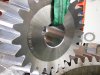
We make gears and normally for drawings, gear teeth just need to look right, not actually be right, as we use gear generating machines to actually make them, but occasionally we need to CNC mill gears from a model so it has to correct.
Introducing my Involute curve generator.
My scripting ability is very small so a lot of it is done manually but the important bit gets done for me.
I have an existing part file with the following circles laid out on it.
Gear OD
Gear PCD
Gear Root Dia
Gear Base Circle
And a Node point.
Make sure the Involute part is open without the sketch activated.
Running the wizoscript brings up a form which asks for the Module, Teeth and Pressure Angle. It will then ask for the addendum. It defaults to the correct standard but allows you to edit it if desired.
Wizoscript will then build a single B-Spline Involute curve on the Gear sketch.
The magic’s done, from here on its all manual work.
I now open the sketch and constrain the node point on the 2nd largest circle (PCD) to the B-spline and adjust the dimension to the reference line to half the desired tooth thickness.
I then mirror the B-Spline around the reference line, giving me the correct tooth shape.
I turn the outside (OD) and 2nd smallest (RD) circles back to solid and trim them and the B-Splines as needed.
One tooth shape!
I’m sure a lot more of it could be scripted but it does what I need, and therefore is useful.
So have a go, even if it’s just to do that 1 tedious step. It can make the difference!