What's new

V11SP1 bugs

steved

Senior Member
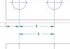
Dimension line offset for hole centres front view is ignored.

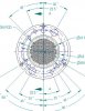
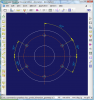
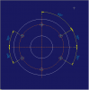
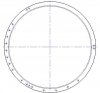
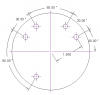
Angular dimensions cannot be applied to centre lines this is a big issue for me as I design parts like the on attached regularly and support inform me that it will not be fixed until V12. I know there is a workaround that involves drawing lines in the view but it gets messy and is time consuming.

Cheers

Steve
 

Attachments

  • DIM ERROR.jpg
    DIM ERROR.jpg
    12.4 KB · Views: 2,189
  • angular dims.jpg
    angular dims.jpg
    49.6 KB · Views: 115

wathavy4

Alibre Super User
I tested if other CAD (you know what) is capable or not.
And I also needed to do a little bit of extra work but at least the angle dimension can be done with Center lines and the extra work is minimum.
 

Attachments

  • 2008-11-03_203506.png
    2008-11-03_203506.png
    81.7 KB · Views: 102
  • Manually moved.png
    Manually moved.png
    10.3 KB · Views: 2,160

steved

Senior Member
I don't know if it's just me but I am finding the current dimension bugs in V11 very time consuming, I have spent the past couple of weeks designing three vacuum chambers to be used on two complete systems that we have in progress.

Now comes the point that I have been dreading, the time to create drawings. It worse than I had had previously I realised yesterday that hole centre lines are now not selectable at all I had hopped that I could waste a load of time applying spurious dimensions to each of the hole centre's in order to activate the nodes and then waste some more time drawing lines over each of the hole centre's using the nodes, but no.

So now I have to draw lines from the centre of the PCD to each hole making my drawing look a mess or make even more work by trimming the excess lines.Attached is a typical view of one part, in the coming week I have many more like it to dimension and it will be a real chore.

I feel we have been totally let down by Alibre with these issues as there does not seem to any will to rectify these issues especially as some of the problems have been introduced or exasperated in V11. I have been using Alibre for five years and my overall satisfaction level as been good, but I have now made a formal request to my employer that we get some new software and move to reduce wasted time producing drawings. :twisted:

End of rant

Cheers

Steve
 

Attachments

  • HOLE CENTRES.jpg
    HOLE CENTRES.jpg
    33.6 KB · Views: 83

NateLiquidGravity

Alibre Super User
I guess I still don't see whats wrong in the pictures or understand the problem. Maybe you could show a before with the problems and the same drawing fixed the right way?
 

steved

Senior Member
Hi Nate

The problem is that i can not aplly angular dimesion to the hole centre's which requires me to have to draw lines to determine thier possition.

Cheers

Steve
 

NateLiquidGravity

Alibre Super User
Ok sorry, now I get it. The quickest way I could come up with is to dimension each hole, delete all the dimensions (center nodes remain), add two lines that were not stuck horizontal or vertical for each hole, midpoint constrain the two lines to each center node, constrain each set of two lines perpendicular, constrain all lines equal, coincident constrain the sets of lines to the center point, and then dimension the angles. Not exactly a fast task.

About your not being able to select stuff while sketching, you should try to right click and edit sketch for that view - at least that is what I had to do to get it to work.
 

JordanCClark

Alibre Super User
What about projecting the design dimensions from the part file? Just a quick thought, but this is what I came up with over lunch.
 

Attachments

  • hole pattern.png
    hole pattern.png
    6.6 KB · Views: 1,427

JordanCClark

Alibre Super User
Leno said:
Ok, next answer and next Username.

Jordan,
Unreasonable.
We speak about 2D Drawings, right?

Ok... Why?

EDIT: I'll admit, I threw this together in about 5 minutes, but the dimensions are there.
 

NateLiquidGravity

Alibre Super User
ralf3 said:
Nate,
Unreasonable.
That was a "2D joke", right?
Huh?
NateLiqGrav said:
Ok sorry, now I get it. The quickest way I could come up with is to dimension each hole, delete all the dimensions (center nodes remain), add two lines that were not stuck horizontal or vertical for each hole, midpoint constrain the two lines to each center node, constrain each set of two lines perpendicular, constrain all lines equal, coincident constrain the sets of lines to the center point, and then dimension the angles. Not exactly a fast task.
I was just spelling out exactly how it can be done for those who don't know yet. And as far as I know it is not a bug. It is a feature that is not in Alibre yet. :!: It is like saying that your car doesn't work right because it doesn't hover off the ground - when that is not even a feature of your car yet.

NateLiqGrav said:
About your not being able to select stuff while sketching, you should try to right click and edit sketch for that view - at least that is what I had to do to get it to work.
Others may not realize this. For a minute there, before I realized what was happening, I was unable to select the nodes in the holes because forgot I had activated the sketch elsewhere and scrolled over to another view.
 

Ralf

Alibre Super User
Nate,

You speak with CAD professionals and not with beginners.
Alibre 2D must be improved.
 

NateLiquidGravity

Alibre Super User
I know that you and many other guys/gals are pros at this but others may be reading this topic and have no idea how to do it manually. And I agree 100% that Alibre's 2d is bad and needs improvements. I believe I have said it before. I've even gone so far as to write my own programs to cover some where it lacks - matter of fact I have one I will be releasing soon.
 

Ralf

Alibre Super User
Nate,

You make me and "Others" more than happy with that and please understand me right.
 
Top