You are using an out of date browser. It may not display this or other websites correctly.
You should upgrade or use an alternative browser.
You should upgrade or use an alternative browser.
Why is direct edit completely useless in V24
- Thread starter drbris
- Start date
HaroldL
Alibre Super User
What are you trying to do with Direct Edit? What "doesn't work anymore"?Direct edit does not work anymore!! This is an essential tool and it used to work well but is useless now. AM I MISSING SOMETHING
NateLiquidGravity
Alibre Super User
Most specifically these changes are mentioned in the help file.
In v23, the standalone Push/Pull Face tool was deprecated and rolled into the Move Face tool as a new option.
In v23, the standalone Push/Pull Radius tool was deprecated and rolled into the Offset Face tool as a new option.
In v23, the standalone Remove tool was deprecated and rolled into the Remove Face tool as a new option.
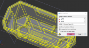
I have a part from SW imported as step. It is a plastic bezel that I need to make a mold for. In the past I was able to fill any holes in the face and then use the remove tool with the option for propagating face to remove the "core" so that I had a solid I could use to boolean subtract a cavity. Then would do something similar to create the core. Sometimes I had to do 1 feature at a time using "select manual faces" to close up the "core" side but it always worked ,eventually. Now it just wants to either select the entire solid if I click the "infer pocket" or if I try to do 1 feature at a time in manual selection it errors out"REM_NO_SOLUTION: gap cannot be filled". Think it would work better if I got the other engineer to send me a parasolid?sss
Attachments
NateLiquidGravity
Alibre Super User
I find things like this work better when done in multiple stages (multiple features) instead of as much as possible at once.
You may also need to check the part when you import it and maybe change your import settings.
You may also need to check the part when you import it and maybe change your import settings.
Maybe so , I am able to remove some features, 1 at a time but others seem to have been done in a bizarre way. It would be so nice if when you did a boolean subtract the floating disconnected pieces were not one lump and could be deleted with the "remove model pieces "- but that only seems to work on imported files.
NateLiquidGravity
Alibre Super User
I use remove model pieces frequently on Alibre made parts.
I have done some experimenting, I built a shelled part with thru holes in AD, then did a project to sketch using the hole edges to create geometry- then since AD does not have ruled surface creation(to close off the holes) I extruded the sketch - .0001" to close off the openings. Boolean subtracted this from a larger plate and used "remove model pieces" to remove the "core" Success. I then exported the part with open holes as a step file ,imported the step into AD and saved as an AD part - however when I try to close off the holes by projecting to sketch (the edges) I get error(INCONS_FACE: inconsistent face-body relationships). Repeat same steps and get ( NO_ATTRIB_INTCOED: unexpected missing attribute on coedge )
I then exported as a para-solid and repeated all of the above steps and Success
????
I then exported as a para-solid and repeated all of the above steps and Success
????
Attachments
simonb65
Alibre Super User
Just as a different approach, and not disagreeing that Alibre lacks some features other package have, that being said, why don't you just use extrude to geometry (far face) and set an offset so you don't break through!I built a shelled part with thru holes in AD, then did a project to sketch using the hole edges to create geometry- then since AD does not have ruled surface creation(to close off the holes) I extruded the sketch - .0001" to close off the openings.


That should work too, although the holes are usually drafted at sometimes weird angles (customer part files). I tried it with this part and it did not work either.So I did an analyze sketch and it says there is an overlap though I can not find it> I just projected to sketch the two arcs that should make the circle and extruded to surface
. So I tried projecting the face as reference and using the center-point of the hole to create a hole sketch using the endpoint of the arc as the second snap point got "ACISERROR_SELF_INTERSECTING_WIRE: Wire is self-intersecting"
Tried using the center-point of arc and the second point outside the original hole to make a larger hole - Now error however also no extrusion either
Attachments


Hi Harold,
I want to close the open ends of the solid(the holes) without removing features, so they can be boolean subtracted from another part (mold plate), Then when you do a "remove model pieces" and select the core you have the cavity side> export that file. Do another "remove model pieces" and select the cavity you have a core side
With this simple part it doesn't save a lot of time but with a part that has lots of features that are very time consuming to " remove face" on all of them (like the one I started this thread with) it would be a great deal simpler to simply close the open holes to create a core and cavity side without a lot of janking around with "remove face".
Even when I get the entire inside of the part closed with remove face to make my cavity. I then have to build a core blank and use the inside of the solid to boolean subtract that to get a finished core.
idslk
Alibre Super User
I'm not an mold expert... (Split line, drafts, etc...?)
anyway
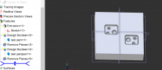
Made an blank and boolean subracted your part:

I exported the result "mold_blank_bottom" as a step-242 and opened in alibre again for the next steps
one:

two:

as an assembly with the original part:

Regards
Stefan
anyway
Made an blank and boolean subracted your part:
I exported the result "mold_blank_bottom" as a step-242 and opened in alibre again for the next steps
one:
two:
as an assembly with the original part:
Regards
Stefan