What's new

Workflow question - how do you initially add assy/parts, and locate them with sensible reference geometries?

Toybuilder

Senior Member
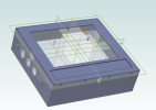
I am working on modeling a control box (see attached image). I have the main box as an assembly, and then there is a top cover assembly which I have started to work on.

When I was a total newbie, I used to just throw a bunch of parts in the top level assembly and often just model in place.

I'm now trying to be more meticulous and methodical. In this design, for example, I have an assembly that represents the main box, and a separate assembly for the top cover.

One of the things I think I need to improve is to set the location and orientation of the reference geometries for new parts (or sub-assys) as I create them.

Right now, I click new-part or new-assy and set that component's name. Then, I go back to the parent assembly that contains this new component and turn on the reference geometry for the new component and will usually use the constraint tool to temporarily "scoot" the component's reference to some feature. When it's just moving along the standard orthogonal directions to mate to a surface, or translating an axis to be concentric to another axis, this is fairly simple. I then delete that constraint, then edit the component to model the part, and then create new constraints based on the actual geometries of mating parts. Is this how you guys do it?

In the example image, I now want to create a part that will be an inlay for the pocket on that front plate. The best I can figure, that would mean I need to first create additional reference geometries in the parent assembly to create an origin centered at the bottom of that pocket. Then, I can follow my usual workflow, I think. This feels all terribly tedious/inefficient and I'm wondering if that's just the way it goes, or if I am being dumb.

I'd love to hear other people's thoughts on this - or referrals to resources where I can learn how to better do this.

Thank you!
 

Attachments

  • 1695315213996.png
    1695315213996.png
    738 KB · Views: 43

HaroldL

Alibre Super User
I don't think I have ever used the top down modeling approach that is sounds like you are using. That said, I think it makes sense for the parts in your assembly to all be symmetrical about the origin. That way when brought into the assembly you can use those default planes for alignment.

For the new insert I would add a new reference plane centered vertically on the cover recess. You can add the plane by editing the cover part and inserting a Point at the mid point of one of the sides. Then create a plane on that point. If the cover is centered on the vertical plane then you won't need to add one centered horizontally on the recess.

When you model the insert use Rectangle by Center to create its sketch. Then its planes will align with the reference planes of the cover.
 

sz0k30

Senior Member
I have always preferred to create an empty ASM first. Then I create either PRT's or SMP's as required on their own, starting with what I think are the more major or important parts working my way down to the more minor parts (nuts, washers). And I try to import them into the ASM in the same sequence. Pretty simple & foolproof (for me anyway).

Maybe just me, but I do not like creating PRT's in the ASM. Seems more prone to mistakes & confusion.
 

Toybuilder

Senior Member
I have always preferred to create an empty ASM first. Then I create either PRT's or SMP's as required on their own, starting with what I think are the more major or important parts working my way down to the more minor parts (nuts, washers). And I try to import them into the ASM in the same sequence. Pretty simple & foolproof (for me anyway).

Maybe just me, but I do not like creating PRT's in the ASM. Seems more prone to mistakes & confusion.
Do you create a tree of ASM's to plan/organize your design and then fill it in with parts?

I think some of this just comes down to me being not as experienced about mechanical design/modeling and not having a process in place yet (hence my post).

What I tend to do right now is to create the PRT in the ASM, create a few sketches pulling projections from other parts as needed, and maybe do a few basic features. Then I edit in a separate window to detail them out before going back to finish modifying them for final "integration".
 

HaroldL

Alibre Super User
Do you create a tree of ASM's to plan/organize your design and then fill it in with parts?

Looking back on my years of enclosure design, the process I would use, somewhat dictated by our PDM system, was to create an indented BOM of the assembly in a spread sheet. Starting with the main assembly at the top, all the subassemblies and parts that make up the top level were listed. Then within each subassembly all the parts that make them up were listed. When that was done there would be a complete BOM in the spread sheet to which part numbers were assigned and entered for the make parts and the PN's and Descriptions of the purchased items/hardware were likewise entered. The size of the finished enclosure was also listed so all the components could reference those size dimensions.

Then working off the spread sheet the modeling would begin, starting with the individual parts and building up to the sub assemblies and final assembly. It's important to use a common starting point for all the parts that will be mated together, like the cover and body, or if there are multiple parts to the body. That makes it easy to put together the assemblies.

One thing that was implemented for some of the enclosure families was the use of Tacton configurator models. When you're designing a family of enclosures that has over 100 different sizes the configurator saved a lot of time when it came time to generate all the models and drawings.

With the use of a Global Parameters File you can do pretty much the same thing. One thing that Tacton allowed was the complete customization of the drawings. All dimensions were assigned a position within the view and drawing so that as subsequent sizes of enclosures were generated from the base model all the drawings updated with the new sizes and dimensions with virtually no clean up required on the drawings.
 

Ex Machina

Senior Member
...

One thing that was implemented for some of the enclosure families was the use of Tacton configurator models. When you're designing a family of enclosures that has over 100 different sizes the configurator saved a lot of time when it came time to generate all the models and drawings.

With the use of a Global Parameters File you can do pretty much the same thing. One thing that Tacton allowed was the complete customization of the drawings. All dimensions were assigned a position within the view and drawing so that as subsequent sizes of enclosures were generated from the base model all the drawings updated with the new sizes and dimensions with virtually no clean up required on the drawings.
I looked up this Tacton company. Very interesting. The thing that you wouldn't be able to replicate in Alibre, without coding custom tools, is the workflow of answering questions and the appropriate value being changed. However, if we ever get Excel support for the Global Parameters file that would work. You could do it with logic and lookup functions along with the built-in configurations in the Design Explorer.

But all in all, I can see how a large company would benefit from a tool like that. It doesn't do anything that Solidworks or Alibre can't already do. But it does it in a way that allows the engineer to prepare the various configurations and then a sales person, with no engineering or CAD background, could select the appropriate ones and generate 3D models and drawings. Clever implementation.

I imagine that it would also generate the model for each configuration. That is actually an underrated capability. To my knowledge, no CAD I know of can do that out of the box. I have only found a custom tool for configurations through Google Sheets for Fusion that did that. But I would really like this capability in Alibre, too. Generate a different file for every configuration or set of global parameters automatically!!!
 

Ex Machina

Senior Member
You can already drive GLP files from Excel...
How? When I first got Alibre, I found a thread about connecting to Excel, and people said that the add-in is no longer functional. Could you direct me to where I can find material on how to connect them?

P.S. I have tried by myself following the instructions on that thread and the help file. But the add-in never worked. Could you please help me with it?
 
Last edited:

HaroldL

Alibre Super User
I looked up this Tacton company. Very interesting. The thing that you wouldn't be able to replicate in Alibre, without coding custom tools, is the workflow of answering questions and the appropriate value being changed. However, if we ever get Excel support for the Global Parameters file that would work. You could do it with logic and lookup functions along with the built-in configurations in the Design Explorer.

But all in all, I can see how a large company would benefit from a tool like that. It doesn't do anything that Solidworks or Alibre can't already do. But it does it in a way that allows the engineer to prepare the various configurations and then a sales person, with no engineering or CAD background, could select the appropriate ones and generate 3D models and drawings. Clever implementation.

I imagine that it would also generate the model for each configuration. That is actually an underrated capability. To my knowledge, no CAD I know of can do that out of the box. I have only found a custom tool for configurations through Google Sheets for Fusion that did that. But I would really like this capability in Alibre, too. Generate a different file for every configuration or set of global parameters automatically!!!
About the time I was retiring the company was adding to, I think, its Concept family of enclosures and updating the drawings. Tacton was used to generate all the models in the family. As I recall the CAD designer would open a master Tacton model, key in the new height, width, and depth of an enclosure model enter part numbers for the body parts, hit Enter and let Tacton create a complete new model with all the drawings. That cut the drafting time from hours down to minutes for each model configuration created. Tacton also made possible the reduction in design time for any custom size enclosures that were ordered by the customer.

Before Tacton some of that work was done by using the equation editor and applying a linked dimensions and equations. The task of cleaning up the new drawings was time consuming.
Using GLP files and Excel to drive various configurations in Alibre seems doable but I'd need to set up a model to see how the work out all the nuances.
 

DavidJ

Administrator
Staff member
Excel add-in works, make sure to install 32 or 64 bit version to match your Excel installation.


From Excel you have to select the current open session of Alibre that you want to work with (the GLP file has to be open in Alibre Design).

If you can't get it to work, submit a support ticket with details. I'll check tickets Monday morning.
 

Ex Machina

Senior Member
I have submitted a ticket before I think. In any case, my tickets go to Ralf.

Does it only work with GLP? If I have a part with user defined variables open, will it pick it up? Also I have a Office365 Business account. I am essentially running MS Office 2019 but it keeps updating as it goes along. Don't know if it has anything to do with. Anyway. I'll check again.
 

NateLiquidGravity

Alibre Super User
Are any add-in planned for LibreOffice Calc or will the Excel add-in work with LibreOffice Calc?
There was a third party one but I haven't tried it in newer versions of Alibre or with the GLP.
 

DavidJ

Administrator
Staff member
One thought that did occur to me overnight - the following add-ins in Excel conflict with the Alibre add-in and must be disabled when using it.

Solver
Analysis ToolPak
Analysis ToolPak VBA

The Alibre Excel Add-in can drive parts, assemblies, GLPs
 

DavidJ

Administrator
Staff member
Default install of Office 365 certainly used to be 32bit (unless 64 bit specifically chosen during install). If not sure, there's information on-line about how to check bitness of the installation.
 

Ex Machina

Senior Member
One thought that did occur to me overnight - the following add-ins in Excel conflict with the Alibre add-in and must be disabled when using it.

Solver
Analysis ToolPak
Analysis ToolPak VBA

The Alibre Excel Add-in can drive parts, assemblies, GLPs
That was it David! That did it! Oh man, this is big! Thank you so much!
 
Top