dlaery
Alibre Super User
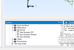
I use the gear geanerator but I don't know how to draw to a gear to a certain diameter.
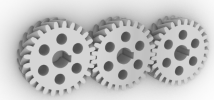
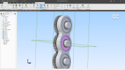
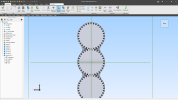
this will be 3 gears in a row
I need them to be 1.85 inches..
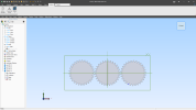
is scaling an acceptable way to get the size I want?
ok, now I realize that Pitch diameter is what I want to use to get the right diameter.
What does the DP and Module represent?
NumberofTeeth = 20
Module = 1.5
PressureAngle = 20
Thickness = 3
NumberofTeeth = 20
DP = 24
PressureAngle = 20
Thickness = 3
this will be 3 gears in a row
I need them to be 1.85 inches..
is scaling an acceptable way to get the size I want?
ok, now I realize that Pitch diameter is what I want to use to get the right diameter.
What does the DP and Module represent?
NumberofTeeth = 20
Module = 1.5
PressureAngle = 20
Thickness = 3
NumberofTeeth = 20
DP = 24
PressureAngle = 20
Thickness = 3