What's new

What approach to take with designing a case top with different side shapes

CMick

Member
Hi there,
I'm brand-new to Alibre Design pro. I have watched some/most of the provided free video content.
This is literally day 1 of my journey with using the program.

I am trying to recreate a case lid as a means of learning the software.
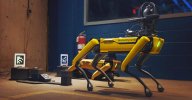
I am trying to approximate or create a toy version of the robot spot dog and end up with a 3D print statue type of output with hopefully some movable parts. Certainly not aiming to re-create a working copy.
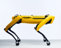
spot robot - side reference.png

spot-charging-dock-industrial-min-1536x803.jpg

I have thought about the following in regards to the large mid section top cover:
- Create a sketch profile of the shape from the front, using offset to create the "thickness" of what was probably originally metal sheet.
- Extrude the sketch towards the back
- Create another sketch from a side of the extrusion detailing out the nice angles and the place where the camera assemblies would go
- Extrude Cut using this sketch

A further detail I noticed is this piece seems to angle outwards towards the camera assembly and is not completely straight up and down, this is perhaps where I am stuck on the most with the current approach I am taking.

Any help or leads to further approaches or materials would be greatly appreciated.
 

HaroldL

Alibre Super User
IF you have images of the robot you could import them and trace the shape. Then use Thin Extrude Boss to create the first feature. Then use subsequent tracings for the side bosses. If there is are changes in the profile from front to back then multiple tracings/sketches on appropriate planes could be used to create a loft and shell since there is no Thin Loft.
 

Stu3d

Senior Member
While I have always considered the best way to learn software is to try and achieve what you want to do as that will be more interesting and fun than plodding through tutorials I agree with Jimcad, this may be a bit ambitious.
I have found the practice models on TooTallTobys website very helpful and fun. You do have to sign up to access them but there are some scattered about on this forum (particularly in the TTT Alibre forum page) and on Youtube videos that you could screen capture to start with. If you model the Youtube ones you could go back and see how the experts tackle it.


These channels all have some TTT model examples done in Alibre, be aware they usually feature the more challenging models.

This is TTT Youtube channel you could capture some models from, if you have questions there are a few people on this forum who have done most of the models and can give tips.

You mention you are brand new to Alibre, have you used other 3d parametric software?
.
 
Last edited:

DavidJ

Administrator
Staff member
I would suggest that a somewhat different approach may have benefit.

Rather than attempting to model a thin cover, instead start with a cuboid representing the main body. Add lumps on the side as needed, either shape the profile sketch or apply chamfers afterwards to get the local shape. Apply fillets to round off the corners, Use an extrude cut if needed to trim away lower regions. Shell the remaining solid to desired thickness, removing faces as appropriate.

I also worry that if you haven't worked with 3D CAD in the past, you'll end up getting very frustrated.
 

HaroldL

Alibre Super User
This is literally day 1 of my journey with using the program.
You didn't mention any previous CAD experience. Is this your first foray into CAD modeling?

If you want practice models/drawings there is also the Timoteo Carreras Soto collection of exercises. I think I have gone through all of them and even posted some renderings of the results in the gallery.


Last edited:

CMick

Member
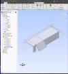
Thanks everyone for the help, I tried the "Thin Extrude" method, I got fairly close with my extrusions, I wasn't able to really comprehend the lofting portion. (Screenshot attached). I didn't bother with the small corner cut-outs as I'm fairly certain I can use a Chamfer feature to get those. I'm just going for half of the case as I think I can mirror it over.

1711500870865.png

I also explored trying to use Rhino 7 as well as Plasticity (Studio) and inserting this whole thing in as a surface. This seemed to not work as I would have expected either. The imported/converted geometry looked messed up and I didn't seem to be able to add drill holes as features from Alibre either.

Honestly and this might be my beginner brain talking here, I did not think this was that elaborate of a case/surface exercise, it really looks mostly straight-on save for the curved out side camera mount piece (The missing piece it seems currently).

I do have some experience in polygonal modelling (there were some comments about what kind of experience I might have had), though this whole CAD thing seems quite different. I could picture doing this in polygon modelling in minutes. I figured the CAD way would be easier to make sure everything prints and fits together in the long run.

I will give the Cuboid and carving method a go next and see how I get on.
 

CMick

Member
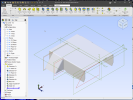
I think I have had success with the Cuboid "DavidJ" suggestion.
My shapes are very rough, compared to the source material, though I think I have a workable approach now (see attached image).

1711509742208.png
Pretty much subtracting or chipping away at a virtual block with various cuts, then adding in the fillets and chamfers to pretty it up a bit.
So I extruded out the largest shape and cut into it to make the flat sides.
This was very counter-intuitive to the way I was thinking and I seem to be missing out on the software doing the measurements (via sketches) for me at times. Though it does seem to at least work out in the end.

Even managed to mirror the whole thing across.

Many thanks for the different ideas, I'll see if I can get something printed out and keep chipping away.
 

Stu3d

Senior Member
I am producing a replica of a 18" F1 wheel. The only detailed drawings I could find online were of 13" Caterham wheels. I was working from photos and then found an stl file on Thingiverse of an 18" wheel which I downloaded, printed and measured. In conjunction with photos I am in the process of remodelling it with details such as correct spokes to match the 1/2 scale Pirelli pole position trophy wheel.
I see there are stl files of the Boston Dynamics robot in various places online, printing a small one of those to measure could help no end.
 
Top