What's new

3 printing - 2 color

Old Geeser

Senior Member
I have a dual print head 3d printer. Does anyone know how to create the 2 files needed. For instance, if you just wanted to print your name in a 3" square. I can create the square and put the text .04 deep into it with a extrude/cut command. But now how do I create the second file of just the text (in the exact same location) with a extrude/ boss command. I've tried copy and paste command but can't get it to work.
Karl
 

Attachments

  • Karl's Box.AD_PKG
    83.3 KB · Views: 2

Ken226

Alibre Super User
There are two ways to go about your contrasting color text infill need.

First method, do so with a dual extruder printer while using each extruder to print a different color simultaneously, you need to create the model body and the text infill as two separate parts. Its best to do this while keeping everything within both parts, in the same place relative to the models coordinate system, to reduce positioning problems later with your slicer.

Example: I took your part and extruded your text 1/8" deeper, to create room for the text model. I then exported this part as a .stl
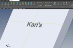
1696968531198.png

Next, I went back to your original part and extruded away everything except the text infill, to a dept of 1/8" and saved it as a .stl:
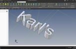
1696968692127.png


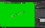
Now, when you import the two .stl files into your slicer, they should be positioned correctly relative to their respective coordinate systems, so you shouldn't need to move anything:
1696969245327.png


With Prusa Slicer it is a little harder, as you have to import the block first, then right click it and add part>load, to insert the text file. Otherwise it antomatically drops them both onto the bed and you can't get the infill to position correctly.

The part files for the block and the text are attached.
 

Attachments

  • Block.AD_PRT
    616.5 KB · Views: 2
  • Text.AD_PRT
    722 KB · Views: 2
Last edited:

Ken226

Alibre Super User
Now, all that being said, I prefer the second way.

I believe it is easier done by switching filament at the appropriate layer. This way, there's no issues with one extruder drooling the wrong color filament onto your print.


Here is an example of a part with text infill, done by switching filament at the correct layer, done on my single extruder Voron 2.4 by using two layers of yellow at the top layer of the text infill.

img_20230923_055301165.jpg


With PrusaSlicer, using my Voron, I can select a color change at a specific layer. When the print job gets to the specified layer it automatically pauses, moves the print head to top, front, center and promps me to change the filament.

Then does it again after the color layer is finished.
 
Last edited:

Old Geeser

Senior Member
Thanks, Ken226 for the help. I believe I have it with your help. I believe you meant "suppressed" instead of "extruded" (under the first picture). I was trying to figure out how to create the second model of just the text, and get it aligned with the block. Then I found a YouTube video on all the changes I needed to make with the slicer. With your models and the slicer set correctly it now looks perfect in the slicer. Now I have to align the two print heads on my printer (a Qidi printer) and make that box a lot smaller and try it out.
Thanks again Ken226
Karl
 

Ken226

Alibre Super User
Thanks, Ken226 for the help. I believe I have it with your help. I believe you meant "suppressed" instead of "extruded" (under the first picture).

No. To create the text only model, I created a new sketch on the front face of your model. I used "project to sketch, maintain association", to create a sketch of the text, and the outer edges of the block. Then used an extrude cut to remove everything except the text.

If you will go through each feature I added in the design explorer, right click / edit, you will see what I did to create each model.
 

Old Geeser

Senior Member
I apologize for bothering you, Ken226, but I am having a hard time understanding what you are doing with sketch 3. I opened a new sketch and then selected the "Project to sketch" function, and selected the faces of the text elements. Are faces what you selected?
 

Ken226

Alibre Super User
I apologize for bothering you, Ken226, but I am having a hard time understanding what you are doing with sketch 3. I opened a new sketch and then selected the "Project to sketch" function, and selected the faces of the text elements. Are faces what you selected?

Yes and no. For sketch 3, I selected the entire face, and the inner portion of the letter A, Project to sketch, Maintain association.

Just one click. Select the whole face. The inner portion of the letter A will be the only face left un-selected. Press the shift key and select it, then your good to go.

1697031440060.png
 

Ken226

Alibre Super User
I made a video of this right quick, it should explain better that text and pics.

Here:

 
Great video but way more work than needed. Prusa will import STL assemblies exported from Alibre. So make the text extrusion part in assembly mode using the bottom of the extruded text cut for the sketch plane. Project to the sketch each letter or easier but 10X slower the surface the letters ore on. Then exit sketch and extrude to the surface. Then export the assembly as xxx.stl. Import into Prussia, highlight the assay and select the To Parts button.
 

Old Geeser

Senior Member
Wow!! What an informative video Ken226! I can't tell you what a big help you have been. I think I understand Ken226's method. If it seems I am not getting back to this very fast is not because I am not interested, it is because we have relatives here for a couple of days (starting today) so I will try and get this accomplished asap.
And I also appreciate the suggestion of bicycleboy. At first glance I am afraid that I also am not understanding his approach either, but I will try and get to his suggestions asap.
Karl
 

Ken226

Alibre Super User
Great video but way more work than needed. Prusa will import STL assemblies exported from Alibre. So make the text extrusion part in assembly mode using the bottom of the extruded text cut for the sketch plane. Project to the sketch each letter or easier but 10X slower the surface the letters ore on. Then exit sketch and extrude to the surface. Then export the assembly as xxx.stl. Import into Prussia, highlight the assay and select the To Parts button.


It took me a try or two to get this method to work, but i figured it out.

The "Split to Parts" button separates the .stl assembly into parts, but it separates all of the text character into individual parts. That isn't a problem though, as you can assign each of them to whichever extruder you want.
 
Last edited:
Top