What's new

Atom 3D - Assemblies - Placing a part (Gage Diameter to a Cone)

itsRick

Member
HI
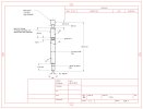
I have this part: 87.54 Depth Glow Plug Ø6 Gage v3-2 REVOVLED SKETCH.AD_PRT (Special thanks to HaroldL).
See sketch: 87.54 Depth Glow Plug Ø6 Gage v3-2 REVOVLED SKETCH.JPG
It will be placed into another model that unfortunately I can't upload, but I have a screen shot of the geometry.
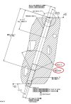
See image: Assembly Section T-T.JPG

The "87.54 Depth Glow Plug Ø6 Gage v3-2 REVOVLED SKETCH.AD_PRT" needs to be inserted into another model but I do not know how to make the Ø6 (Datum B) of the Glow Plug Gage (Sketch) mate to the Cone for the Ø6 Gage Diameter in the jpg image (Assembly Section T-T.JPG).
The cone angle of the Glow Plug gage (Sketch/Model) is 90° while the cone angle of the jpg image (Assembly Section T-T.JPG) is 93°. The angles of either part can't be altered, this is by design for the Tooling Ball concept.
The model attached is basically a Tooling Ball.

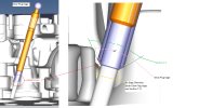
I have anchored the "Other model" and am able to insert the "87.54 Depth Glow Plug Ø6 Gage v3-2 REVOVLED SKETCH.AD_PRT" aligned to the location where it is to be insert/mated.
From there is where I need assistance to set the depth location.

All help, hints, etc is appreciated.

(I am on a Trial Version for evaluation).
 

Attachments

  • 87.54 Depth Glow Plug Ø6 Gage v3-2 REVOVLED SKETCH.JPG
    87.54 Depth Glow Plug Ø6 Gage v3-2 REVOVLED SKETCH.JPG
    202.2 KB · Views: 20
  • 87.54 Depth Glow Plug Ø6 Gage v3-2 REVOVLED SKETCH.AD_PRT
    319 KB · Views: 7

Ex Machina

Senior Member
If both cones end at a ∅6 diameter, that is where they will theoretically touch. So you just select those 2 edges and apply a fastener constraint. If the 93° is slightly larger (only way this could work. smaller wouldn't even go in) it is a bit more complicated. You need to create a plane, normal to the tools axis, at the exact minor diameter of the 93° cone. Then you assemble the edge of that minor diameter and the plane.

The way you would do that is the following:

-Go to the design of the "87.54 Depth Glow Plug Ø6 Gage v3-2 REVOVLED SKETCH.AD_PRT".
-On the 90° cone you want to have mate with the 93° cone, draw a reference line vertical to the parts axis of symmetry. One point of the line should be coincident to the line of the cone in the sketch.
-Dimension that line to be equal to the minor diameter of the 93° cone.
-Make sure the midpoint of that line is on the axis of symmetry of the part.
-Create an axis based on that line using the "Insert axis from linear sketch figure" tool.
1691768759547.png
-Exit the sketch, rebuild and create a plane
-Use the axis you just made and a plane normal to the axis of symmetry of your part as inputs, in your case, it's the ZX plane.
-Create the plane

Now you can constrain the bottom edge (minor diameter) of the wider cone to the plane of the "87.54 Depth Glow Plug Ø6 Gage v3-2 REVOVLED SKETCH.AD_PRT" you just created. The constraint is parametric. When you change the dimension of that reference line in the cone, the plane will shift and the constraint will rebuild to match the new position of your part.

If you use global parameters to link the minor diameter of the 93° cone to the dimension of that reference line I described above, the entire thing can be adjusted parametrically by adjusting the value in the Global Parameters file.

If that last part is too advanced, skip it. You don't need it, it's just a nice-to-have.

If you don't understand what I mean by the steps above, let me know and I'll make a video about it. It's actually pretty quick if you know what you need.
 

HaroldL

Alibre Super User
I modeled an 'assy' part with 'half' of the slanted hole into which I constrained the pin using a Coaxial constraint. The selected the bottom edges of the chamfers in both parts and applied a Fastener constraint.

First thing is to make the edges visible: (Thanks Ex Machina for that tip)

turn on edges.jpg

Then apply the constraints:
apply constraint.jpg
 

Attachments

  • New Assy with Pin.AD_PKG
    102.7 KB · Views: 1

HaroldL

Alibre Super User
I came to me after I posted my previous comments and images that all you should need is the Fastener constraint to locate the pin in the hole. So I remodeled the assy part so the hole is within the body then recorded this short video on how to use the Fastener constraint to position it in the hole.


itsRick

Member
I apologize for any confusion, I tried to convey the information as best I could, maybe these images will clear some things up.
See images:
T-T CAD 1.JPG
T-T CAD 2.JPG

This CAD was modeled in Calypso software, extremely cumbersome to do.
This is why I am testing Alibre.
 

Attachments

  • T-T CAD 2.JPG
    T-T CAD 2.JPG
    109.5 KB · Views: 21
  • T-T CAD 1.JPG
    T-T CAD 1.JPG
    509.7 KB · Views: 21

evandene

Member
First, center axis to center axis, than tangent to circel.
Or
Center to center, than edge to edge?
Be careful, a fasteners quick and dirty Mating will screw you change the assembly. (F.e. changing center distance) A ALIBRE fasteners Constrain is always under constrained.
 

HaroldL

Alibre Super User
I tried adding a plane a constraining the edge of the chamfer to the plane but that didn't work. Neither did using the Fastener constraint, that left a gap and the pin was out of position per the drawing Assembly Section T-T.

So after studying the drawing a bit more I came up with the steps that I recorded in this video.


And for you to have something in-hand to see the parts I used in the video, here's a package file of the assembly.
 

Attachments

  • Offset Gage Pin Constraint.AD_PKG
    97.2 KB · Views: 2

Ex Machina

Senior Member
Hey Rick,

Here's a video on the method I describe above. To make the plane in the "Pin" part, you can either use the axis tool I show in the video or the Point tool Harold shows in his. The point might be a bit more elegant actually.


P.S. I have now attached the package file of the assembly shown in the video.
 

Attachments

  • Cones Mating.AD_PKG
    71.4 KB · Views: 0
Last edited:

idslk

Alibre Super User
Hey Rick,

good solution from konstantinos, but you can "save" some steps :)

start at the "inner part" sketch:
1691841673595.png

1691841792748.png

on "outer part" sketch:
1691841870225.png

1691841885621.png

on assembly.

first contraint the part to coordinate system (bore ond shaft on same axis) with reference geometry turned on:
1691842035457.png

constraint the 2 reference points:

1691842107788.png

result:
1691842165918.png


Regards
Stefan
 

HaroldL

Alibre Super User
Hey Rick,

Here's a video on the method I describe above. To make the plane in the "Pin" part, you can either use the axis tool I show in the video or the Point tool Harold shows in his. The point might be a bit more elegant actually.


P.S. I have now attached the package file of the assembly shown in the video.
Konstantinos, How you demonstrate setting up the reference geometry in the pin is the same way I initially thought. I then tried to mate that reference plane to the bottom edge of the chamfered hole. When that failed I completely forgot about adding the reference point in the hole that you added.:oops: Then in my last video I set up the reference plane and point based on the section T-T image that Rick posted.

Using your method makes sure the two chamfers are in contact. The point that I inserted at the top of the hole and the plane I added at the top edge of the pins chamfer can be used for inspection of the assembled model.

BTW, have you ever worked as an instructor? The way you present the info in your videos sounds like you have.
 

Ex Machina

Senior Member
Hey Harold,

In my Upwork profile, I have done many training contracts for CAD and CAM. But I have also taught to under and postgraduate students and I even lectured on a preparatory course on Matlab for the M.Eng. program I was attending, for the new guys.

As for the plane and circular edge. If you look at my first post, that is exactly what I went for. Not sure why it doesn't work. But that was my first thought too. I went to make the video and saw it failed.

And in any case, your approach was the one a seasoned engineer would take. Follow the print, right? If it's in the print, it's in the print for a reason.
 

itsRick

Member
Thank you to all who assisted.
I tried adding a plane a constraining the edge of the chamfer to the plane but that didn't work. Neither did using the Fastener constraint, that left a gap and the pin was out of position per the drawing Assembly Section T-T.

So after studying the drawing a bit more I came up with the steps that I recorded in this video.


And for you to have something in-hand to see the parts I used in the video, here's a package file of the assembly.
Thank you.
How can I get a copy of your video?
 

itsRick

Member
HarlodL and idslk both exposed a design flaw for me.
I believe idslk approach shows a truer instance of the flaw in this image: Depth design flaw exposed.png
I will have to get the Gage designer to change the 90° to 87° to get the contact wear point that was intended.
I don't know how I over looked this.
 

Attachments

  • Depth design flaw exposed.png
    Depth design flaw exposed.png
    12.8 KB · Views: 9

itsRick

Member
I tried adding a plane a constraining the edge of the chamfer to the plane but that didn't work. Neither did using the Fastener constraint, that left a gap and the pin was out of position per the drawing Assembly Section T-T.

So after studying the drawing a bit more I came up with the steps that I recorded in this video.


And for you to have something in-hand to see the parts I used in the video, here's a package file of the assembly.

While writing down instructions, I noticed I do not have menu items you have, most likely because I am on trial software?
I have managed to get a new Glow Plug design in place at entry where it 87.54mm offset should take place.
The problem is, I cant get it to move but one direction, away from the mating part. I used "Reverse" but it has zero effect, once the offset has been enabled that's all I get.
I have to use "undo" to return to the original starting point.
 

Attachments

  • New Assy with Pin Rev2.AD_ASM
    234 KB · Views: 1

HaroldL

Alibre Super User
Rick, you need to Package the assembly for uploading.
From the File menu or the File Ribbon tab: File>Package>Create
then upload that file. You shouldn't need to zip it before uploading.
 
Top