What's new

Best approach for this part

steveastro

Senior Member
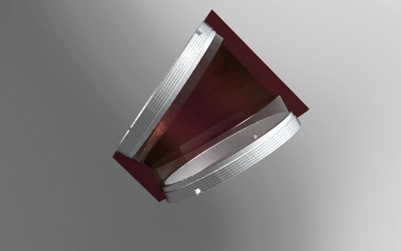
I've attached what is a special lens cell for an optical project. If someone would like to look, at its heart is a sketch tied to a 2D arrangement of lenses tipped and shifted to each other. There is no single rotation of cut that would make this, so the second and third sketches are rotated cuts about the axes of each lens, with a final op to cut through an approximation of the centre to leave a clamping edge.
I copied and pasted the sketch from 1 to the other 2, but noted that the link to the original sketch in subsequent copies was lost, and therefore I locked all the lines in the sketch copies.

I just feel this isn't an optimal method. Does anyone have any other ideas ?
 

Attachments

  • corrector 3.AD_PRT
    219.5 KB · Views: 14

Oldbelt

Alibre Super User
Its a good practis to have all sketch lines turned into green, meaning the whole sketch should be constrained.
you have only very few green lines.
The part can be created with extruding only, why use revolving ??
 

Attachments

  • corrector3-Oldbelt.AD_PRT
    339 KB · Views: 4

HaroldL

Alibre Super User
Did you start your sketches in a Top Down method? I ask because the model is so far from the origin and is on a plane that is not apparent in the Design Explorer.

If you're not looking for accuracy but just workflow, I took some measurements of your part and the defining sketches and worked out a method that has a few more steps so may not be more optimal. I started with a couple of angled planes that I then extruded to. For your part, the distance between these planes will need to be known in order to properly place them. The rest of the Extrude Cuts were sized and positioned from measuring your model. Again, knowing some key dimensions, like the angle between the lenses and distance apart, would make these steps more accurate.

corrector 3 SAMPLE.png
 

Attachments

  • corrector 3 SAMPLE.AD_PRT
    354.5 KB · Views: 6

steveastro

Senior Member
Did you start your sketches in a Top Down method? I ask because the model is so far from the origin and is on a plane that is not apparent in the Design Explorer.

Yes, Top Down, there is a complex optical layout which affects the relative positions of the lens, mirrors and focal plane of the system, and which is spreadsheet driven.
 

Oldbelt

Alibre Super User
Harold my point is that sketches shall be constrained, what ever the color is for a complete constrained sketch.
I can't see your approach to this part is the simples way to do it, I don't think you have seen my solution.!!
I took also Measurements from the original parts, placed far away from the global origo.
Whatever a "top-down" method or anything else is used , it is good practice to build parts around origo.
 

steveastro

Senior Member
Whatever a "top-down" method or anything else is used , it is good practice to build parts around origo.

I too find it a PITA when the origin of a new part is displaced like this, but it seems fundamental to the arrangement of parts in an assembly that stays properly constrained.
 

sz0k30

Senior Member
Just my 2 cents from many years of experience, it is always better to build individual parts at the origin of the part and not the assembly.
 

steveastro

Senior Member
Whilst the conversation is interesting and informative, its seems to me, that the simplest way to do this would be a mechanism to automatically use a master sketch as the foundation for the works on the part, and there doesn't appear to be a mechanism for it.
 

HaroldL

Alibre Super User
Harold my point is that sketches shall be constrained, what ever the color is for a complete constrained sketch.
I think you meant this comment for Simon. I do agree that, as a preferred workflow, having fully constrained sketches avoids issues later on in the design process.
I can't see your approach to this part is the simples way to do it, I don't think you have seen my solution.!!
If you read my post I did mention that my method "has a few more steps so may not be more optimal." And no, I didn't see your solution before I posted. However I did just now take a look and it seems just like steveastro's except using Extrudes instead of Revolves.
the simplest way to do this would be a mechanism to automatically use a master sketch as the foundation for the works on the part, and there doesn't appear to be a mechanism for it.
I would think that Project to Sketch would work, not automatically, and then there are those interdesign constraints that can have issues.
 
Top