What's new

Can we please get Min and Max functions

Stuart

Senior Member
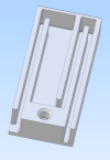
In this part, a PCB module goes in the large opening and wires go in the narrow slots.

The depth of the openings, and therefore the thickness of the whole part, needs to be the greater of the cable and PCB.

Because we still don't have MIn and Max functions, I ended up with a bad part because I accidentally used the smaller of the two dimensions.

This is just the most recent of the many cases where I needed Min / Max and why I started asking for it years ago.

Am I the only one that wants Min and Max functions in the equation editor? I can't understand why two extremely simple but very useful functions can't be added.
1698871769992.png
 

HaroldL

Alibre Super User
:confused: Aren't the MIN/MAX dimensions called out on the drawing? And IF there was a MIN/MAX function in the EE can you explain how it would be used? Don't you design to allow for a MMC of the model and take the related parts into consideration? And if you are exporting a STEP model how would they be transferred/exported?
 

simonb65

Alibre Super User
+1 A min and max in the equation editor would certainly be a welcome addition.

@HaroldL I think the OP is after something like an equation that is along the lines of Depth = max(CableDia, PCBHeight) so that you have full flexibility in how dimensions are driven. You change the cable dia and it automatically extrudes less or more based on the equation. Also, if you are exporting the model for 3D printing, you don't even create drawings!
 

HaroldL

Alibre Super User
+1 A min and max in the equation editor would certainly be a welcome addition.

@HaroldL I think the OP is after something like an equation that is along the lines of Depth = max(CableDia, PCBHeight) so that you have full flexibility in how dimensions are driven. You change the cable dia and it automatically extrudes less or more based on the equation.
I see your max example but do you then need another one for min? I'm no equation guru but can't you link cable diameter and PCB size to the extrusion now thru the use of other equations and variables?

Also, if you are exporting the model for 3D printing, you don't even create drawings!
That's why I asked about exporting STEP?
Just trying to understand.
 

Stuart

Senior Member
I see your max example but do you then need another one for min? I'm no equation guru but can't you link cable diameter and PCB size to the extrusion now thru the use of other equations and variables?
There's only a single design variant. Both a cable and a circuit board need to fit in a space. In order for both to fit, you need to use a dimension that is the greater of the two dimensions.

The cable size may change, and the circuit board dimensions may change, so by using the maximum of both for the extrusion cut distance there is always going to be enough space for both to fit.
 

JimCad

Senior Member
So if Cable has a limit of +- 1 & Board has a limit of +-1
The Depth = (CableDia, PCBHeight)+2
or am I missing something ?
That's how I'd do it anyway.
Jim
 

simonb65

Alibre Super User
I see your max example but do you then need another one for min?
It's exactly the same with just the word changed and the smaller of the two values returned, rather than the larger of the two! i.e. D10 = min(CableDia, PCBHeight), Although not a good example for the OP's use case unless you wanted to boss extrude an insert in the lid to fill the space above the PCB/Cable whilst leaving the cavity in the base a fixed depth!
 

Stuart

Senior Member
So if Cable has a limit of +- 1 & Board has a limit of +-1
The Depth = (CableDia, PCBHeight)+2
or am I missing something ?
That's how I'd do it anyway.
Jim
This isn't about tolerances. It's about the hollowing out of the block deep *enough* to accomodate both the wire and the PCB, regardless of which one is bigger.
 

Stuart

Senior Member
So if Cable has a limit of +- 1 & Board has a limit of +-1
The Depth = (CableDia, PCBHeight)+2
or am I missing something ?
That's how I'd do it anyway.
Jim
If you wanted to include the tolerances it would be Max(CableDia + 1, PCBHeight + 1).
 

DavidJ

Administrator
Staff member
For the specific Max case given above, there is a straightforward workaround - repeat the extrude cut from starting plane/face with each dimension used in one feature. The deeper cut will define the final model.

Not as easy for Min....
 

Stuart

Senior Member
For the specific Max case given above, there is a straightforward workaround - repeat the extrude cut from starting plane/face with each dimension used in one feature. The deeper cut will define the final model.

Not as easy for Min....

What's the work-around for the case where the slot width needs to accomodate two wire sizes? In this part, there are two wires that go in the left slot. They are different sizes. I manually chose the larger wire size for the slot width, just as I chose the greater of the wire and PCB for the depth. I only brought up the wire vs PCB because that's the one I mistakenly picked the wrong size.
 

DavidJ

Administrator
Staff member
It gets more complex, the number of features will increase. You'd have to have 2 sketches for the profile, with slot width defined in each using the alternate values.

I wasn't trying to minimise your request - just pointing out that in SOME cases it is possible to get the desired effect.
 

Stuart

Senior Member
It gets more complex, the number of features will increase. You'd have to have 2 sketches for the profile, with slot width defined in each using the alternate values.

I wasn't trying to minimise your request - just pointing out that in SOME cases it is possible to get the desired effect.
That's exactly why the function would be so useful. Two "Max(X,Y)" instead of two detailed sketches and four extrusions.

Why do simple but powerful functions like this never get implemented? I'd much rather have this than new toolbar graphics.
 

JimCad

Senior Member
This isn't about tolerances. It's about the hollowing out of the block deep *enough* to accomodate both the wire and the PCB, regardless of which one is bigger.
I thought that's what I was saying.
The Depth = (CableDia + PCBHeight)+2 in the model.
Then add tolerance to the drawing or am I still missing something?
Jim
 

Stuart

Senior Member
I thought that's what I was saying.
The Depth = (CableDia + PCBHeight)+2 in the model.
Then add tolerance to the drawing or am I still missing something?
Jim
You're adding +2. It's the Max of (X + 1, Y +1) == Max (X, Y) + Max (1, 1). You only want to use the +1 of the one value used, X or Y, not the +1 from both X and Y.
 

Stuart

Senior Member
Stuart - I'm not arguing with the validity of your request.
Can you find out why my long standing request has never been implemented? As a software developer, I know time isn't the issue. Is it that not enough people would use it?
 

DavidJ

Administrator
Staff member
Stuart - how was your request logged/submitted? I only have access to one of the systems that tracks Development items . I'm not part of the development team

There are always more requests than there is resource to implement so it may well be that nobody else has asked for this functionality, so it never made it 'up the list'. But that is speculation.
 

Stuart

Senior Member
I don't remember how it was submitted, probably an email back before Alibre was sold. I've wanted it from day one.
 
Top