What's new

Change relationship between front and top view ?

Mfroejd

Member
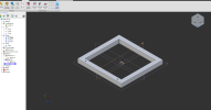
I'm barely two weeks old with Alibre and coming from fusion 360. Maybe I'm missing something but I have an issue with the views in the cube, I dont understand why the top view is rotated 90 degrees? It,s not the biggest deal in the world, but just now while working i was switching between front and top view and didn't realise that the view rotated while switching between them. Which made me draw the next scetch in the wrong orientation because the rectangle has similar but not equal sides.

Can I change this so when I press "Down" from the top view I go to front view instead of Left?

Edit: Changed title.
View cube.png
 
Last edited:

jfleming

Alibre Super User
At the very least, the user should be able to reassign what is "top" . For some reason Alibre treats "Y" as the up. It is annoying for sure
 

simonb65

Alibre Super User
For some reason Alibre treats "Y" as the up. It is annoying for sure
+1, Totally agree ... and it's a long standing issue that has sparked debate over the years.

An X-Y Plane with Y being UP is only applicable if your looking at a computer monitor or drawing board (in 2D).
Most things in the 3D printing and real world (automotive, aerospace, etc, PCB assemblies, etc), Z is the vertical (height) axis, with X-Y being the horizontal ground plane! ie. Front shows X = left/right+, Y = near/far+, Z = up+/down. Where-as Alibre shows Front as X = left/right+, Y = up+/down, Z = near+/far.

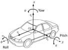
From ISO 8855-2011

1635768373762.png

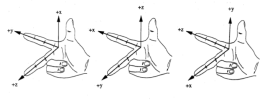
Even the right hand rule permutations don't match the AD system unless your pointing vertically upwards with a twisted wrist!

The middle one shows the axis system used by ISO 885-2011, from the drivers viewpoint ...

1635768712778.png

A method of custom assigning XYZ direction, Top, Front, etc the UI axis system would solve so many issues.

EDIT: It would be really interesting to hear from Alibre dev, what 'standard/industry sector/personal idea' the current AD co-ordinate system is actually derived from.
 

DavidJ

Administrator
Staff member
There is no single 'Industry Standard'.

I don't know specifically where the current AD coordinate system was copied or derived from (that was before I started using it at v8.1).

Architecture tends to favour Z perpendicular to screen.

Automotive and Aerospace have other preferences.

Machine tools - Z is always the spindle axis, so depending upon the machine different orientations are possible (compare a lathe to a vertical mill).

Some of this is probably a carry over from 2D paper drawings where having X & Y in the plane of the paper makes sense - for early CAD products at least the screen was simply representing a piece of paper (it just happened that the face of the screen was approximately vertical).

Which direction you regard as 'UP' when looking at a 2D representation will vary depending upon context - compare a Map with a drawing of a Tree.

I'm not arguing that Alibre's co-ordinate system is 'right', but neither is any other.

This is a personal viewpoint - it doesn't necessarily match the view of Alibre, LLC.
 

sz0k30

Senior Member
When I worked in the Automotive Industry, The "X" "Y" plane was the screen. "Z" was coming out at me. So as far as I'm concerned, Alibre is correct!
 

jfleming

Alibre Super User
Might I ask why it does this also? I rotate the view around to sketch on the correct plane so that Z is positive, then when you activate sketch it spins it around 180 degrees so that Z+ is going down???
 

Attachments

  • rotated.gif
    rotated.gif
    1.7 MB · Views: 14

simonb65

Alibre Super User
When I worked in the Automotive Industry, The "X" "Y" plane was the screen. "Z" was coming out at me. So as far as I'm concerned, Alibre is correct!
Machine tools - Z is always the spindle axis, so depending upon the machine different orientations are possible (compare a lathe to a vertical mill).

Some of this is probably a carry over from 2D paper drawings where having X & Y in the plane of the paper makes sense - for early CAD products at least the screen was simply representing a piece of paper (it just happened that the face of the screen was approximately vertical).
Both make sense, but then it depends on what you consider is the 'Top' and 'Front' of an object. The 'Top' to me means looking vertically straight down on the object, which will differ based on tool paths and the co-ordinate system. So, the ability to assign Top, Front, etc would cater for all end uses.

Some great point too there @DavidJ. I think context IS definitely the key.

In @sz0k30's case, with that orientation, I would expect to be drawing everything looking down (from the Top), but that view in Alibre is the Front view! How do you communicate to others or create a 2D drawing if the orientation is not what someone else is expecting?

I 3D print and also create PCB assemblies, and whilst you can rotate the part on the print bed for slicing or rotate the model in bigger assemblies, I find it intuitive that the Z axis is the height component (as all the components on a PCB have an X and Y placement on the board and 3D printers have a vertical tool axis), which means for me, looking down is the z axis and I would consider that the 'Top' view. Alibre however, tells me that's the 'Front' view, which makes zero sense! It can be a little unintuitive at times and so to enhance Alibre would make it easier to work with.

Matlab is a classic tool that easily allows you to define your own axis labels and directions, because it caters for every end application, and it makes the process intuitive.

I guess it's a discussion topic that will always continue to divide opinion and cause unnecessary confusion to newbies. :)
 

HaroldL

Alibre Super User
This "argument" about which way is Up in Alibre has been going on for a few versions as I recall. It should be noted that it is possible for users to create custom views if they wish or need, at least in Pro and Expert. I haven't tried it but I think if you created custom views in a template then they would be available for all your parts. I know Alibre doesn't have templates, per se, for Part, Assembly and Sheet Metal workspaces but you can create and save a file with all the views set the way you want, then, for each new part, open the file, SAVE AS to the new part name and go to work. I do that for some of the sheet metal parts I made. I have a "template" with the bend data for Aluminum and some Mild Steel parts that have saved me from having to reenter bend parameters for all the new parts. Maybe that would work for setting view orientations too.

And, BTW, the orientation that @sz0k30 described in his post #6 is how I was taught in Technical College and has been used on all the CAD systems I have used be it AutoCAD, I-DEAS, SolidWorks or Alibre. To me it is normal and would take some time to get used to some other orientation. Knowing how Alibre orients its views I create parts how they will be or are oriented in the final assembly model and move on.
 

bigseb

Alibre Super User
Might I ask why it does this also? I rotate the view around to sketch on the correct plane so that Z is positive, then when you activate sketch it spins it around 180 degrees so that Z+ is going down???
That is weird. Never noticed it before.
 

bigseb

Alibre Super User
WRT the axis direction thing... personally its not an issue for me. It's been suggested before that it should user definable and not hard-coded, good idea. But I still think AD has some deeper issues that need to be addressed before anything else.
 

simonb65

Alibre Super User
That is weird. Never noticed it before.
I've noticed many times that if you select a face then activate 2D sketch mode, the model spins around and shows you a view from the rear of the face, rather than the side you selected. Then you have to use the tool to spin it all 180 deg.
 

bigseb

Alibre Super User
Just had a closer look at that... actually not so weird after all. Behaves as it should considering no further instruction was given than to have the normal of the plane point at the user. X+ Z- is one way to do it. By having the Z axis point up X has to be -. Software behaving as instructed.
 

HaroldL

Alibre Super User
Well, until Alibre has some 1-click solution, you could also use Orient to Plane before starting a sketch. That way the view won't spin around to an orientation that you don't want.

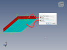
This:
otp.png


Results in this:
otp done.png


And Reset View gives this:
reset view.png
 

JST

Alibre Super User
It may be relevant to mention that Alibre comes with Keyshot.

Keyshot defaults to up being Y.

Perhaps it would be wise to default Alibre to work with Keyshot?

And, Lo and Behold, that's how it is!
 

simonb65

Alibre Super User
And, Lo and Behold, that's how it is!
That's because historically virtual computer coordinate systems have always been X and Y are the screen (where 0,0 is the Top, Left corner ... Y being opposite polarity to a graph or paper based 2d system because thats historically how CRT rasterisation works!) and Z represents the depth. That however, doesn't equate to physical CAM or other real world coord systems!
 

jfleming

Alibre Super User
Well, until Alibre has some 1-click solution, you could also use Orient to Plane before starting a sketch. That way the view won't spin around to an orientation that you don't want.

This:


That's fine Harold but not if you're starting with an empty slate, or have round/tubular geometry to start with.
 

JST

Alibre Super User
At the very least, the user should be able to reassign what is "top" . For some reason Alibre treats "Y" as the up. It is annoying for sure
You can, of course, set up a part with ANY orientation vs the original planes.

It seems there are two different issues here.....

1) what axis YOU use to orient the part top. You can use ANY axis as "up" when you start a part, and orient the model vs the base axes.

2) what axis Alibre uses as the default for "top".

It does not bother me, since I really never use view orientation except for inserting drawing views.
 
Top