What's new

How to make a plane at an angle

Garryp4

Member
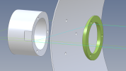
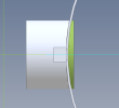
Please look at the assembly drawing as then my question should be obvious. The part Optic Holder will be screwed to the can wall with three screws. The shown hole was easy as it is simply perpendicular to the can wall. However, the other two holes will need to be at an angle so the screw heads are flush with the inside wall of the can. I can not figure out how to get a plane at the angle to draw a screw hole in.

Thanks
 

Attachments

  • Optics Holder.AD_PRT
    350.5 KB · Views: 12
  • Can_Optic.AD_ASM
    223 KB · Views: 7

HaroldL

Alibre Super User
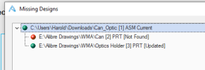
You need to create and upload a package of the drawing, assembly, and part. With your assembly drawing open go to File>Package>Create. That will pull everything together in a package file.

1703806302157.png
 

HaroldL

Alibre Super User
I had to redo this video to explain the steps taken to get the holes aligned normal to the surface of the can. The previous one had a error in my method, this one I think is better for the screw hole alignment.


EDIT: check my latest video below for additional steps for creating the holes on the surface.


As another solution, have you thought of having a concave washer on the inside so all the screw holes are straight?
Which level of Alibre do you have?

Exploded view
1703830569517.png


Assembled view
1703830697143.png
 
Last edited:

HaroldL

Alibre Super User
After giving this some more thought I recorded this video showing two methods for creating the circular hole pattern on the curved surfaces.
It should be noted that for Atom 3D, while I didn't create new holes on the small stub part, the method shown on the large tube part can be duplicated for the stub.


Garryp4

Member
Harold:

At 13:29 in the video you select "Insert Point From Sketch". I can't seem to find that option in Atom 3D.
 

Attachments

  • Optics Holder.AD_PRT
    333.5 KB · Views: 1

HaroldL

Alibre Super User
As far as I know you should have that tool available in Atom 3D. Although I can find nothing in the Help manual that specifically explains Insert Point From Sketch.:confused:

If you select Insert Point outside of a sketch you will be presented with a different workflow and dialog.
You must be editing or creating a sketch for this particular function to work. While the sketch is active check on the Sketch Ribbon for the Insert Point icon:
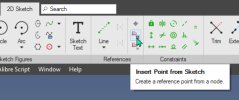
Insert Point From Sketch.jpg

And also from the Sketch Menu (if you have them active):
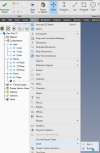
Insert Point From Sketch Menu.jpg

Another thing you can try is to either convert the reference line from the arc node that is tangent to the cylinder to the origin or create it as construction geometry (solid line). Then, while still in the sketch, select menu Insert>Plane. It will create a plane on the line and give you the option to move it along the line. Move it to a position that at the end of the line tangent to the cylinder. Once you have that plane inserted exit the sketch and start the sketch for the hole on the new plane. There will be a Black dot at the origin of the plane where you should place the sketch for the hole thru the cylinder wall.

 
Last edited:

NateLiquidGravity

Alibre Super User
Menus are only available in Alibre Design Professional and Alibre Design Expert. I'm not sure if Sketch > Insert Point is or not.
 

Ken226

Alibre Super User
If I understand your question, your trying to create a plane tangent to the cylinder, at an angle to the default plane?

Like this?


When you use the "insert plane" tool, you will either need to turn on sketch visibility so you can select the radial, or you can simply select the appropriate sketch from the design explorer.

My video is just a video version of the method that Harold described in the last paragraph of his last post. Hopefully he didn't charge you 550$ :)
 
Last edited:

Garryp4

Member
Thanks for the reply!

The $550 is the cost to upgrade from Atom. Harold was most helpful. I must not have explained what I am trying to do very well. I am making the small part that will screw onto the tube, but can not figure out how to make two screw holes that are not perpendicular. Is there a way to extend the radial line onto the smaller part? Since I could not figure out how, I went with Harolds suggestion of a concave washer. I am back and forth which is the better idea.
 

HaroldL

Alibre Super User
If you use the same method to create a sketch pattern on the small part as on the large tube. Then "wrap" the hole positions to the curved surface as I show in the video and create the reference sketches and planes. Then create the holes on those planes and they should align between the two parts. Just be sure to create the planes for the holes in the tube on the outside surface.
If you want or need, I can create another video for you showing the procedure. Let me know.
 

Ken226

Alibre Super User
I'm not doing anything else at the moment.


Keep in mind, im moving through it kinda fast and not taking time to measure, align, dimension, etc. When you create these features on your own part, you will have to work out the geometries, angles, locations, etc. To make sure everything aligns. I think that in the assembly environment, this may be easier if you constrain the parts into the actual final positions relative to one another.
 
Last edited:

Garryp4

Member
I don't seem to have the 'project to sketch' feature in Atom. A search in the search bar comes up with nothing. There does not seem to be any references between the different parts when one is 'active'.
 

Ken226

Alibre Super User
In your sketch ribbon, it isn't there?

The help shows it in the user interface.unless that is a mistake. But, I seem to remember it being there, when I had Atom.

And the documentation doesn't indicate it is absent from Atom.

It wouldn't be the first time my memory was wrong though.


Sketch ribbon, third button from the left

Screenshot_20240105-170001.png
 
Last edited:
Top