David_K
New Member
Hello,
I was working on a part the other day that involved the use of a helix. I didn't have a problem pre se with the helix itself, but with a feature added on to the end of it. I need to have the parameters of the helix (OD, Turns (fractional), Length, etc) flexible, so the added feature needs to follow the end of the helix around the helix axis as any of those parameters get changed. The added feature was a sweep of the end profile of the helix form along a guide curve that started from a point on the end face of the helix. The problem I ran into was the sketch for the feature was either flipping orientation, the sketch was ok but the sweep was rendered incorrectly, or a flat out error.
So, I created a test model to experiment with the situation - see attached part file. To begin with, the helix sketch is done from a plane that is set at the helix lead angle. This is calculated in the Equations (fx). Control of the helix parameters are also done within Equations. Setting up the helix profile this way ensures that the sketch form maintains its proper dimensions and proportions clear to the end of the helix. This is not necessary but is my design intent in this example. I also made the helix form a truncated circle so that it was something other than a basic geometric shape, in case that might have masked some condition.
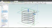
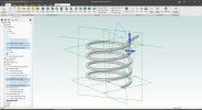
The current test part has two features on the end of the helix - one that curves upward (End1 Curve) and one that goes outward (Outboard Curve). I did this to see what differences there might be between the two in that they are approximately at right angles to each other - only different by the lead angle. The mis-behavior between the two can be different for a given set of helix parameter changes, but they eventually end up with the same kind of problem result. I have attached two screen captures showing the helix and end features, one as initially modeled and one showing the failure of both where the Turns of the helix was changed from 5 to 4.1. The End1 Curve flipped (rendered correctly for that) and the Outboard Curve rendered wrong. Its guide curve was still correct, however. (The two highlighted planes are the feature guide curve sketch planes) What's more interesting is that the features can be "walked" aroung the helix in smaller increments (say a quarter turn) for that total amount of change and they maintain proper orientation and rendering. The display of the sketch planes don't stay as original though.
I cannot say for certain what is going on but it appears like these sketch planes have some sort of coordinate system within them and the translation of the planes around the helix make it appear that they "pinwheel" around the helix end face point. The construction of the planes and axis are as independant of the model coordinate system as best as I can get them. Maybe I'm missing something there.
Has anyone encountered this kind of problem? Might there be a method I cannot envision right now to keep the sketch planes (and the sketches) oriented correctly as they "orbit" around the helix? Might this just be an inherent behavior of Alibre and its underlying geometric engine with little or no hope of overcoming it?
Any advice that is offered will be greatly appreciated. Thanks.
I was working on a part the other day that involved the use of a helix. I didn't have a problem pre se with the helix itself, but with a feature added on to the end of it. I need to have the parameters of the helix (OD, Turns (fractional), Length, etc) flexible, so the added feature needs to follow the end of the helix around the helix axis as any of those parameters get changed. The added feature was a sweep of the end profile of the helix form along a guide curve that started from a point on the end face of the helix. The problem I ran into was the sketch for the feature was either flipping orientation, the sketch was ok but the sweep was rendered incorrectly, or a flat out error.
So, I created a test model to experiment with the situation - see attached part file. To begin with, the helix sketch is done from a plane that is set at the helix lead angle. This is calculated in the Equations (fx). Control of the helix parameters are also done within Equations. Setting up the helix profile this way ensures that the sketch form maintains its proper dimensions and proportions clear to the end of the helix. This is not necessary but is my design intent in this example. I also made the helix form a truncated circle so that it was something other than a basic geometric shape, in case that might have masked some condition.
The current test part has two features on the end of the helix - one that curves upward (End1 Curve) and one that goes outward (Outboard Curve). I did this to see what differences there might be between the two in that they are approximately at right angles to each other - only different by the lead angle. The mis-behavior between the two can be different for a given set of helix parameter changes, but they eventually end up with the same kind of problem result. I have attached two screen captures showing the helix and end features, one as initially modeled and one showing the failure of both where the Turns of the helix was changed from 5 to 4.1. The End1 Curve flipped (rendered correctly for that) and the Outboard Curve rendered wrong. Its guide curve was still correct, however. (The two highlighted planes are the feature guide curve sketch planes) What's more interesting is that the features can be "walked" aroung the helix in smaller increments (say a quarter turn) for that total amount of change and they maintain proper orientation and rendering. The display of the sketch planes don't stay as original though.
I cannot say for certain what is going on but it appears like these sketch planes have some sort of coordinate system within them and the translation of the planes around the helix make it appear that they "pinwheel" around the helix end face point. The construction of the planes and axis are as independant of the model coordinate system as best as I can get them. Maybe I'm missing something there.
Has anyone encountered this kind of problem? Might there be a method I cannot envision right now to keep the sketch planes (and the sketches) oriented correctly as they "orbit" around the helix? Might this just be an inherent behavior of Alibre and its underlying geometric engine with little or no hope of overcoming it?
Any advice that is offered will be greatly appreciated. Thanks.