Hi all, first post here. Recently purchased Alibre Pro v25. I have some previous experience with mostly 2D work, but new to Alibre as will become quite obvious shortly.
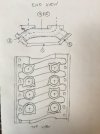
I’ve taken in all the sketching and most of the modeling tutorials. I have some questions. Attached is a sketch of an intake manifold flange. The rounded rectangular features are the port windows and wall thickness for the transitions to the runners. The points are the locations of the mounting bosses. There will eventually be a right and left flange as they are not completely symmetric.
I built the geometry by using a centered square with fillets applied to the corners. I constructed one of the port windows with the flanges scallops about the origin then copied it to the other three positions. I tried to move the figures and could not. After a couple hours of experimentation, I gathered the figures about the origin seemed to be constrained about the origin although I saw no such constraint. I searched the forum and found a thread that said it was possibly an implied constraint.
Q1: How do I see an implied constraint? Or do I just never build something around the origin that I intend to move? I solved it by working from the copies and deleting the original built about the origin.
The design exporer only displays points I've created (and sketches?) but doesnt contain sketch construction history features like rectangles, copying them, etc.
Q2: I take sketch details other than points are not cpatured in the design explorer? Correct?
Somehow, apparently when I saved the file, I lost all the sketch construction geometry and it became just a joined sketch, whereas before, I could see the nodes where all the lines, fillets, and tangencies occurred.
Q3: I did not intentionally do this. Why did that happen? Upon saving the skecth? Is there a command I can use to explode the sketch back into its constituent construction parts? I’d like to be able to edit it and measure to and from it. In my previous CAD work there were join and explode commands for such things. Is there in Alibre?
Another odd thing was after I constructed the rounded rectangles, and used analyze, it reported that there were overlaps, intersections and open loops. I understood the scallops being open looped, but not on the rounded windows since they were built with the rectangle and fillet commands. If there were such things on those features, it seemingly came from the fillet command being applied to the rectangle? No healing fix available but the joined sketch tests fine. ?
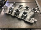
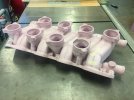
It’s no big loss to start over at this point since it’s not much work to replicate, and I’d probably layout nodes to center the port windows (and edit I’d like to do). I just figured I may as well practice on something I actually want to build. This sketch will eventually get extruded for flange and runner interface, and get mounting bosses added. The runners lofted and shelled down a spline to the carb interface, but I need more time in the sketching saddle.
All help appreciated.
Best,
Kelly
I’ve taken in all the sketching and most of the modeling tutorials. I have some questions. Attached is a sketch of an intake manifold flange. The rounded rectangular features are the port windows and wall thickness for the transitions to the runners. The points are the locations of the mounting bosses. There will eventually be a right and left flange as they are not completely symmetric.
I built the geometry by using a centered square with fillets applied to the corners. I constructed one of the port windows with the flanges scallops about the origin then copied it to the other three positions. I tried to move the figures and could not. After a couple hours of experimentation, I gathered the figures about the origin seemed to be constrained about the origin although I saw no such constraint. I searched the forum and found a thread that said it was possibly an implied constraint.
Q1: How do I see an implied constraint? Or do I just never build something around the origin that I intend to move? I solved it by working from the copies and deleting the original built about the origin.
The design exporer only displays points I've created (and sketches?) but doesnt contain sketch construction history features like rectangles, copying them, etc.
Q2: I take sketch details other than points are not cpatured in the design explorer? Correct?
Somehow, apparently when I saved the file, I lost all the sketch construction geometry and it became just a joined sketch, whereas before, I could see the nodes where all the lines, fillets, and tangencies occurred.
Q3: I did not intentionally do this. Why did that happen? Upon saving the skecth? Is there a command I can use to explode the sketch back into its constituent construction parts? I’d like to be able to edit it and measure to and from it. In my previous CAD work there were join and explode commands for such things. Is there in Alibre?
Another odd thing was after I constructed the rounded rectangles, and used analyze, it reported that there were overlaps, intersections and open loops. I understood the scallops being open looped, but not on the rounded windows since they were built with the rectangle and fillet commands. If there were such things on those features, it seemingly came from the fillet command being applied to the rectangle? No healing fix available but the joined sketch tests fine. ?
It’s no big loss to start over at this point since it’s not much work to replicate, and I’d probably layout nodes to center the port windows (and edit I’d like to do). I just figured I may as well practice on something I actually want to build. This sketch will eventually get extruded for flange and runner interface, and get mounting bosses added. The runners lofted and shelled down a spline to the carb interface, but I need more time in the sketching saddle.
All help appreciated.
Best,
Kelly

")