Im not sure why it's not extruding for you. I un-suppressed the sketch and clicked extrude, and it extruded
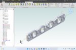
Doh! It was simply because sketch 6 was (inadvertently) suppressed. I also had the angle of the plane for one of the sets of bosses which I corrected. The intake flange is now essentially complete except trimming away the excess boss geometry and maybe some filleting.
Rather than inserting a bunch of points and using those as references, dimension one of your port loops horizontal and vertical sketch figures relative to the default X and Y axes. (I created my first loop on the origin, which causes inferred constraints which lock down its position). From that point, you can use the constraints and dimensions to lock everything else down relative to those. Ideally, you'd like to have your sketch constrained so that future modifications will be much easier.
The blueprints I'm working from are from the intake face of the cylinder head, so all the positions of features translate to the backside of the intake flange. The primary datum on those drawings is actually a reference 3-space point on the engine block which doesn't translate very sensibly in many respects to the intake manifold, but I have used them to avoid a lot of dimensional translation......though suboptimal.
An ideal sketch would be all black, with each figure having its magnitude and position defined.
I took note of fully defining sketches from the various tutorials though struggle a bit to do so, and when I do, I seem to run into other problems downstream caused by the constrained objects......but I'll keep at it.
Hint: One thing you might try is to create an offset planes, from planes 18 and 20, by the distance you want the ports to extend. Create your sketches on those offset planes then extrude "to geometry" and select a face on the flange as the target. That way you won't have so much trimming to do to get your final shape. And for trimming try out the Remove Face tool, that way you won't have to set up sketches and extrusions to remove the extra bits you don't want in the model.
Thanks for that. I updated the file attached below (updated rev 5) but have not trimmed off the excess bosses. I can certainly see how it be better to just avoid it altogether with the extrude to geometry suggestion. Removing the bits in the scalloped areas looks tricky. Where is Remove Face Tool? I have design Pro. Is that an Expert feature?
As for all the Point errors. If you RMB click on them and select Status from the popup menu they all have the same "The source of this geometry is not found" status. Somehow, it seems,the nodes that were used to locate the points have gone missing and need to be replaced.
Yes I surmised such but not sure how the nodes disappeared unless I was dragging the feature/sketches around in the design history.
Hint: So you don't end up with a complex and complicated sketch, sketch and create on feature then use Feature Pattern to create the rest of the features. That way if you need to modify the the feature you only have one simple sketch to change and all the remaining features will update accordingly.
I will definitely give this a go on my next revision. The Alibre documentation for Pattern says "Only dimples, sheet metal cuts, and holes should be patterned." but I noticed in the tubular header example that Ken226 posted that doesn't seem to be the case. I wasn't success using it in my first attempt. It wants to copy the feature to a liner grid, and although the two sets of bosses are linear, they are not equally spaced, so I would have to apply a pattern for the second, third, and fourth boss in each set....is that correct? The Port windows are equally spaced. It would be very nice to be able to change the size of the port window and face of the bosses and have the model update, so I'll have to work on this.
I'm sure I'll build refine this part a few more times as it is my first part and learning exercise.
Thanks for your help fellas. I'm making some progress.
Best,
Kelly