What's new

Trigonometric Functions in the Equation Editor

Nautilus

Member
trigonometric.jpg

Hi, I'm new to the forum. I've only been using Alibre for a short time, although I have a lot of experience with other CAD programs.

Can the equation editor use trigonometric functions?

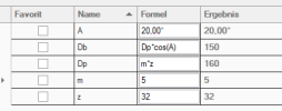
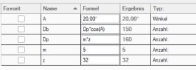
Apparently, yes. But it does something weird. If you multiply Dp*cos(A)=160x cos(20) you should give 150.35
However, it gives that result multiplied by 10

Can someone clarify this for me?
What's going on?
 

Ex Machina

Alibre Super User
It would seem that all of the numbers in that equation are natural numbers, i.e. do not have any units. That in turn means that the Db value you're trying to calculate does not have any units but you are trying to use it as a length. That is why the error is thrown. Now, why the result appears 10 times larger is a long conversation without particular meaning since the equation has thrown an error already.

Try multiplying by 1mm at the end of that expression to force it to inherit the desired mm units. It should work. If not, let us know what it did.
 

idslk

Alibre Super User
depends on the Units...(forum search for equation editor and units...)
1710340290357.png
hint...:
1710340341749.png

may you show us your "complete Editor window

Regards
Stefan
 

DavidJ

Administrator
Staff member
Note that internally Alibre works in cm as the (distance) model units for any natively created file. Imported files can have different model units.


Nautilus

Member
trigonometric.jpg
I get it to work. But it doesn't seem logical to me. I have to divide Dp1 and Dp2 by 200...? absurd
In other equation editors I've worked with, this isn't necessary. AutoCAD, BricsCAD, SolidWorks, Catia...
 

DavidJ

Administrator
Staff member
What are you actually trying to calculate? It isn't very clear to me. (EDIT : that is to say what physical thing, not just the equation)

Please share either the file, or at least a view of equation editor with all rows visible.
 
Last edited:

Nautilus

Member
trigonometric.jpg

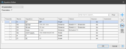
I try to calculate the dimensions of a gear to intertrace the teeth by 2 methods:

-Grant's Method
- Approximate layout of the involute profile

The table I currently have is this. But there are obviously many more calculations to be done.
 

DavidJ

Administrator
Staff member
Sorry - not familiar with either.... you probably haven't picked an easy first attempt.

For gears there are a couple of probably simpler options - David's add in as per post #10, and even the example gear generator script that is part of Alibre Pro & Expert. I know the options in the standard Script are not comprehensive, I have slightly modified versions that cover the other ways you might want to use the standard gear formulae. I can provide the tweaked scripts.

I can usually get the equation editor to 'behave' - but I'm just not clear what you actually want to achieve.
 

DavidJ

Administrator
Staff member
Here you go - the secret is not to do too much in any one step, particularly any casting of types.

EE image.jpg
 

stepalibre

Alibre Super User
You don't need the "one" parameter Dp1*mm will work the same.

My rule of thumb is:
All equations/formulas are Scales.
Count is only used for integers (the result of the equation would be an integer)
Any unit can be used in a equation independent of the file unit used.
Distance parameters require a unit.
 
Last edited:

stepalibre

Alibre Super User
Coming from other CAD systems:
Distance = dimension variable that require a unit
Angle = angles
Count = integers, instances
Scale = variables, global variables
Other CAD systems automatically add units to equations based on the file units. I like Alibre's approach to equations especially for configurations and design libraries. It definitely has a learning curve!
 
Last edited:

bolsover

Senior Member
As it happens, I'm working on an update to my utilities package to include a tool to generate rack and pinion gears.
The utilities already has a tool to generate external spur/helical gears so the update just needs to generate the appropriate rack.
As usual, a template file can be of great benefit especially when there are features needed that are not part of the standard API.
In this case, it is the linear pattern - but it seemed appropriate to put the whole model into a part. The utilities add-on will use this part and set the appropriate parameters before a call to regenerate the part.

This is just some test code - but you'll get the idea..

C#:
 private void BuildRack(object sender, EventArgs e)
        {
            var fileData = GetRackDetails();
            var filePath = GetAlibreFilePath(fileData.SaveFile, fileData.Template);
            var session = InitAlibreFile(filePath);
            session.Parameters.OpenParameterTransaction();
            session.Parameters.Item("Alpha").Value = Radians(20);
            session.Parameters.Item("Beta").Value = Radians(0);
            session.Parameters.Item("Module").Value = 2.5 * 0.1;
            session.Parameters.Item("RackTeeth").Value = 25;
            session.Parameters.Item("Width").Value = 10 * 0.1;
            session.Parameters.CloseParameterTransaction();
            ((IADPartSession) session).RegenerateAll();
           
        }

Template file is attached.

David
 

Attachments

  • HelicalRackTemplate.AD_PRT
    943.5 KB · Views: 2
Top