What's new

Trouble with sketches

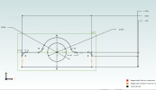
with more regularity than i'd like i'm having trouble getting a sketch completely defined. i've got one right now that has two sides that are equal, symetric etc that are orange and i cannot get them black!!
Tried dimensioning, adding one constraint or another, (perp, equal, parallel)

I've attached a screen shot which is a PNG it's so simple it's embarassing!

Is there a way to get Alibre to show me what it is whining about?
 

Attachments

  • pillow block.PNG
    pillow block.PNG
    45.1 KB · Views: 31
Last edited:

wazzu83

Senior Member
A couple of things come to mind ...
1) Check the sketch and make sure it is closed and there are no errors.
2) Sometimes I have to close the sketch and re-open to overcome what you are seeing. It's like Alibre is slow to respond to a fully constrained sketch.
 
A couple of things come to mind ...
1) Check the sketch and make sure it is closed and there are no errors.
2) Sometimes I have to close the sketch and re-open to overcome what you are seeing. It's like Alibre is slow to respond to a fully constrained sketch.
thanks a million!! I wish it would simply "show" now like it does sometimes???
 

simonb65

Alibre Super User
They are orange because, whilst you have defined the distance between them, you haven't defined a distance or constrained them to the centre vertical axis. So, essentially, if you picked up the orange lines you could move them left to right.

1646250677003.png

or define the length of one or both of these ...

1646250767298.png
 

Ralf

Alibre Super User
Position undefined -> DOF indicator on your screenshot, and if you have made some double sketch lines (on top of each other) -> Analyze Sketch, as shown as in my post above.

Position-undefined.png
 

wazzu83

Senior Member
1646250767298.png

I get that the dimensions are missing, but why do the 2 circled segments show as Fully Defined?
 

Ralf

Alibre Super User
Hi Wazzu,

We still await the 3D Part with the 2D Sketch in question, as already asked by David.
Screenshots help to answer general questions, but in detail, it is only possible with the file.
 

simonb65

Alibre Super User
I've just drawn and constrained this from the original post dimensions, and it all becomes fully defined! ...

1646259797019.png

Not sure why the original post has this tangent constraint being shown??? ...

1646259856313.png

... as that horizontal line is only tangential to the 0.1" radi on each end !!

The 2 symmetric constrains I used are on the centres of the radi ...

1646260030645.png

So, not sure what's going on in the original post without seeing the part file!
 

HaroldL

Alibre Super User
Either add an Equal constraint between the two short lines at the top of the rectangular shape - OR - add a Symmetric constraint between the two Orange lines and the Y axis
 
Rather than make us guess what is wrong, perhaps post the file here...
Hi Wazzu,

We still await the 3D Part with the 2D Sketch in question, as already asked by David.
Screenshots help to answer general questions, but in detail, it is only possible with the file.
what i think i need on this one is to simply attach the gear to the shaft? Then i have another jack shaft that gets another gear!?
 

Attachments

  • gear snip.PNG
    gear snip.PNG
    175.9 KB · Views: 11
I've just drawn and constrained this from the original post dimensions, and it all becomes fully defined! ...

View attachment 35489

Not sure why the original post has this tangent constraint being shown??? ...

View attachment 35490

... as that horizontal line is only tangential to the 0.1" radi on each end !!

The 2 symmetric constrains I used are on the centres of the radi ...

View attachment 35491

So, not sure what's going on in the original post without seeing the part file!
i got it to be happy when I redrew it. Am going to use the analyze function because i think that will help me find the glitches, i sure don't want to have to redraw everything!!
 
Top