What's new

UI proposal - feedback requested

evandene

Member
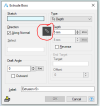
Great initiative for having a look at consistency and efficiency. In regard to efficiency, would it be possible to add a measured distance, radius or angle as an input?
The measuring symbol aside the input for calling out the measuring tool could do the job. The measuring tool itself should be able to transfer (copy) as the required depth. This functionality could be added in a consistent way for all value inputs.
1695655517618.png
 

voxelman

Member
As with all UI overhauls be sure that user adoption is optional. No, I am not kidding. Whatever your good intentions, I have invested thousands of hours learning to use the software like it is. The devil you know is always better than the one you don't. Sure some of the dialogs aren't ideologically pure or clunky but I have learned to work with them as they are and at 73 and counting with something like 17 years of Alibre use under my belt I'm not up for learning a whole new regime of Dialogs.
 

Old Geeser

Senior Member
I am not sure this is a UI problem but when you "export" a file to an "STL" file the file is sent to the location of the "dog bone" not the end of the file. I have been burned twice now as I don't discover the problem until the part is finished 3D printing.
 

Ex Machina

Senior Member
Great initiative for having a look at consistency and efficiency. In regard to efficiency, would it be possible to add a measured distance, radius or angle as an input?
The measuring symbol aside the input for calling out the measuring tool could do the job. The measuring tool itself should be able to transfer (copy) as the required depth. This functionality could be added in a consistent way for all value inputs.
View attachment 39772
That is a double-edged sword actually. Because if you want to extrude for a length that already exists in model, there is a parametric way to go about it, for sure. Whereas, if you measure you get a snapshot of how things look now and any future changes are not followed.

Now that I think of it Alibre team, you know what would hit it out of the ballpark completely..? If you could turn measurements from the measurement tool (Ctrl+M) into parameters... Now that would be a whole different level!!!
 
Last edited:

NateLiquidGravity

Alibre Super User
No need for that. You can already make a sketch, add the dimensions you need as reference parameters, and then use them later in equations

I've used it many times including assemblies that automatically adjust arrays to fill in more items when a part length changes.
 

NateLiquidGravity

Alibre Super User

Ex Machina

Senior Member
Measurment in assemblies..png

I think it works just fine. Now it would be better if it had more functionality and you could select an axis to project that measurement. But that 5.8310" measurement is precisely why I would want that as a parameter. To skip making that sketch.

P.S. I have figured out long ago that the measurement tool always measures the smallest distance between entities. Trying measuring 2 different circular edges along a shaft. The number almost never match up. But if you know what to expect, it can be immensely useful.

P.S.2 You need to make a plane on that "Face 4" and then select the plane and the edge of the second part, and then you get the 5" number you're after. Probably selecting the face would give the same result.

1695900281740.png
 
Last edited:

Max

Administrator
Staff member
That is a double-edged sword actually. Because if you want to extrude for a length that already exists in model, there is a parametric way to go about it, for sure. Whereas, if you measure you get a snapshot of how things look now and any future changes are not followed.

Now that I think of it Alibre team, you know what would hit it out of the ballpark completely..? If you could turn measurements from the measurement tool (Ctrl+M) into parameters... Now that would be a whole different level!!!
I’ve been thinking of this. It’s kind of akin to the “pick whip” in adobe after effects. Probably would get dicey though as it’s subject to geometry naming changes, eg it gets its value from Edge45 but if Edge45 gets reassigned by ACIS it just messed up the model probably in a way that is hard to tell.
 

Ex Machina

Senior Member
I’ve been thinking of this. It’s kind of akin to the “pick whip” in adobe after effects. Probably would get dicey though as it’s subject to geometry naming changes, eg it gets its value from Edge45 but if Edge45 gets reassigned by ACIS it just messed up the model probably in a way that is hard to tell.
OK, I get that. But if I select Edge45 for a fillet, let's say. How does Alibre keep track of it? Isn't this solved already for features, for example?

P.S. CAD user not coder here. Just offering my opinion.
 

Max

Administrator
Staff member
OK, I get that. But if I select Edge45 for a fillet, let's say. How does Alibre keep track of it? Isn't this solved already for features, for example?

P.S. CAD user not coder here. Just offering my opinion.
Well, sometimes it doesn’t keep track of it!

That’s why fillets fail if you muck too much with the geometry above them.

Generally speaking, it works insofar as you are using good modeling practices and never make significant geometry changes, but that’s not real life. Fillets fail, this would too in certain similar circumstances.

Trust me I want this to work. But it is full of potential gotchas. It’s possible the quantity of gotchas is acceptable to most people most of the time. We just really just need to think through it and convince ourselves this won’t turn into something that is way more trouble than it’s worth. Eg tons of forum posts and support tickets asking why the model messed up after making a change and why doesn’t this work. Most people do not (nor should they need to) understand the intricacies of ACIS entity naming, but that also means they don’t understand why things sometimes break, which makes them think it’s buggy etc.
 

HaroldL

Alibre Super User
@Max, Here's a late entry for suggestions on the dialogs. Instead of having a drop-down list for the Type in the Boss and Cut dialogs, replace the drop-down list with a series of Radio buttons or Check Boxes. That way all the options are visible at a glance without having to click the drop-down to open it and then select the Type you need/want. At the least it will save one mouse click, if anyone is counting.

This may be an enhancement request but for the Dual Depth Type, can To Geometry and To Next be added for each direction. And have each "To" direction be independent of each other. That would be so very useful. The work around now is to go To Geometry/Next in one direction then start a new sketch and Project to Sketch the previous sketch and go To Geometry/Next in a second direction. That is time consuming and prone to error.
 

OrjanB

Senior Member
On my wishlist: Isometric dimensioning
Mentioned several times in the past - still of interest.
I sometimes want to dimension the isometric view in a drawing.
This can be useful when making drawings for people not being familiar with reading standard projections.
Implemented in not too far future?
 

Ex Machina

Senior Member
This may be an enhancement request but for the Dual Depth Type, can To Geometry and To Next be added for each direction. And have each "To" direction be independent of each other. That would be so very useful. The work around now is to go To Geometry/Next in one direction then start a new sketch and Project to Sketch the previous sketch and go To Geometry/Next in a second direction. That is time consuming and prone to error.
This is something that would seriously enhance the functionality of the extrude command. I have needed that very often and I do the workaround the Harold describes. Would be a "Level Up" moment to get that!
 

DavidJ

Administrator
Staff member
Can I remind all that this thread relates to specific proposed UI changes - it isn't a catch all for enhancement requests.

If you have a specific enhancement request or similar that is not directly to do with the original subject of this thread, either start another thread (to discuss or to gage popularity), or submit a request via support.
 

bolsover

Senior Member
@Max
I just went back to your original post having read through the later comments.
One issue stands out - I think previously mentioned by @stepalibre..
The 'Style' of the Design Explorer now seems at odds with the new dialogs. Is it intended that this be updated also? And, will it also be dockable?
I have often wished that it was possible to detach the Design Explorer from the main window and drag to a second screen. Having said that, I realise it could get confusing if several windows are open concurrently. Some other software I use has recently introduced the ability to change the colour of the window header - great help when several projects are open at once.
Screen grab to illustrate..
Screenshot 2023-10-06 160628.png
 

HaroldL

Alibre Super User
Can I remind all that this thread relates to specific proposed UI changes - it isn't a catch all for enhancement requests.

If you have a specific enhancement request or similar that is not directly to do with the original subject of this thread, either start another thread (to discuss or to gage popularity), or submit a request via support.
I added it kind of as an after thought and noted that it was an enhancement request. But to your suggestion I did start a new thread in the Feedback section.
 

MDG

Member
My suggestion is that you remove all the drop-down menus in these small windows, they are to hide information and require an additional click.
Regarding selection boxes, these are so small and communicate nothing, replace these by icons is also good as suggested by NateLiquidGravity.
Visual information which communicate, order, less clics is great.
Direct seen of icons is much better and the picture of the icon is good for communicate the type. When mouse over icon display explanation help in text is the good help. A frequent flow of top to down, left to right is great improvement.
 
Top