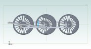
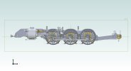
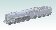
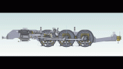
Has anyone had any success in modelling Walschaerts valve gear ? I keep reaching a point where constraints become over defined no matter how much I change the order of assembly or way parts are structured into sub assemblies. There are no design relationships, patterns or arrays in any sub assembly that is flexible.
You are using an out of date browser. It may not display this or other websites correctly.
You should upgrade or use an alternative browser.
You should upgrade or use an alternative browser.
Walschaerts (Resolved)
- Thread starter shmbry
- Start date
Hello Harold.I'd be interested in the set of drawings you used to create the valve assembly. I'm always up to a challenge, especially the old technology.
PM sent.
I have found a resolution.

Previously my assembly logic was to replicate what would happen in the real world whereby the connecting rod assembly would be coaxially constrained by the three crank pins therefore rotation of any of the axles would be transmitted to the others. It appears Alibre does not share this logic and at some point through the rest of the assembly it would seize up and throw an over definition.
At the seventh attempt I got the entire assembly to work. I constrained the connecting rod assembly to one crank pin and then constrained the ZX plane of the connecting rod assembly to the ZX plane of the main assembly using a free offset. I then constrained a plane of a wheel to the like plane of its neighbour, also using a free offset. Thereafter smooth running.
In systems such as these, it's very, very easy to end up with a circular chain of constraints (think of a snake biting its own tail). Now physically in the real system that doesn't matter - but mathematically the 'closing constraint' in the circuit is redundant (or at least partially so - it may be partly required to set a position or orientation). In addition to the mathematical redundancy, the constraint solver doesn't have an obvious starting point in the chain to work from.
Using less restrictive constraints in some part of the circuit can help - maybe constrain to a point, rather than an axis OR to an edge/axis rather than a flat face. When constraining items together, it's all too easy to inadvertently duplicate an existing aspect of previous constraints, leading to 'over-constrained'.
For the case shown by Stephen coaxial constraint to one crankpin implies that connecting rod will be parallel to the wheels - adding a similar constraint to another crankpin duplicates that implied parallelism and will give 'over constrained'. Constraining a point in the connecting rod bore, with the axis of a crank pin would not duplicate the implied wheel to con-rod parallelism. Some of this will depend upon exactly how other parts/sub-assemblies were constrained.
These issue can be very tricky to spot the cause of, so I always advise that as soon as any constraint fails investigate immediately. Going back one step, or re-specifying the last constraint done is reasonably straightforward, if things are left until more constraints are added it rapidly becomes almost impossible to diagnose the issue.
Can you post a quick video of it working?I have found a resolution.
View attachment 39165
Previously my assembly logic was to replicate what would happen in the real world whereby the connecting rod assembly would be coaxially constrained by the three crank pins therefore rotation of any of the axles would be transmitted to the others. It appears Alibre does not share this logic and at some point through the rest of the assembly it would seize up and throw an over definition.
At the seventh attempt I got the entire assembly to work. I constrained the connecting rod assembly to one crank pin and then constrained the ZX plane of the connecting rod assembly to the ZX plane of the main assembly using a free offset. I then constrained a plane of a wheel to the like plane of its neighbour, also using a free offset. Thereafter smooth running.
You could use your phone if no capturing software.
Jim
I would like to, however I have no means of animating it. I didn't want to go to the expense of an addon. I could do it in Blender but I haven't got round to it yet. As you can see it's quite complex and I would rather be able to animate it where constraints are implemented. I admit I haven't explored Keyshot yet, I'm concentrating on modelling and then drawings.Can you post a quick video of it working?
You could use your phone if no capturing software.
Jim

Last edited:
HaroldL
Alibre Super User
I think animating the model in KS would be a huge task. It would be super nice if KS would/could import the constraints but that is not possible Rotating parts is not the issue, it is the linkages that need to rotate and stay centered on their respective pivots.I admit I haven't explored Keyshot yet,
NateLiquidGravity
Alibre Super User
@idslk attached a short AlibreScript for running an animation in Alibre Design in this thread: https://www.alibre.com/forum/index.php?threads/motion-studies.21013/#post-134869
You just need to screen record as it happens.
You just need to screen record as it happens.
Many thanks Nate.@idslk attached a short AlibreScript for running an animation in Alibre Design in this thread: https://www.alibre.com/forum/index.php?threads/motion-studies.21013/#post-134869
You just need to screen record as it happens.
I will have a look at that. Hopefully there are some instructions.
For others who also may be interested the instructions are here:
Script Manual.
And an exercise manual:
Exercise Manual
Script Manual.
And an exercise manual:
Exercise Manual
Last edited:
Hi JimCor!
What else can I say?
Cor!
You've spent a LOT of time on that.
ARe they doing a competition this year?
You should enter that!
Jim
I will enter it, but not necessarily this year. I don't know when the competition is and it's not a high priority. I bought Alibre in November last year having retired in 2020 and therefore not having daily access to Solidworks. The principle aim is the verify the paper drawings the model is based on before committing to cutting material for the end product of a 5" gauge live steam locomotive. Thus far, although I haven't kept a record it has taken approx. 700 hours. I anticipate about 30 - 40 A1 drawings in the future. The model engineering fraternity tend to use a lower number of drawings but incorporate several parts in one view with a lot of hidden detail and no assembly drawings.
I was part of a team designing water treatment plant for the marine industry. Mainly cruise ships.Hi Jim
I will enter it, but not necessarily this year. I don't know when the competition is and it's not a high priority. I bought Alibre in November last year having retired in 2020 and therefore not having daily access to Solidworks. The principle aim is the verify the paper drawings the model is based on before committing to cutting material for the end product of a 5" gauge live steam locomotive. Thus far, although I haven't kept a record it has taken approx. 700 hours. I anticipate about 30 - 40 A1 drawings in the future. The model engineering fraternity tend to use a lower number of drawings but incorporate several parts in one view with a lot of hidden detail and no assembly drawings.
I used Inventor and now have Alibre but too busy to practice with it yet.
Need more time!
Jim
Well The script works, and not too painful to implement. as I can't insert a media file here I have posted a video on another site. I am not sure if it can be downloaded. Hopefully it can be as it is painful to watch at the original speed therefore I suggest you download it and watch it at a higher speed. I had to set the script to a small increment of rotation as Alibre has a problem keeping up. If you study it closely you will see that the centre crank pin (which is being driven) moves and then the rest of the assembly catches up. However it is a very promising start and hopefully I can use similar scripts to move and verify various controls and articulations without trying to drag parts on screen and waiting for eons to see if Alibre can get its head around what I'm trying to do.
Last edited:


