You are using an out of date browser. It may not display this or other websites correctly.
You should upgrade or use an alternative browser.
You should upgrade or use an alternative browser.
When reopening after saving, the bearing shafts lose location and I'm forced to redo the concentric restraints
- Thread starter conservativetrolls
- Start date

conservativetrolls
Member
Thanks for your time. I'm seeing some other issues now.!
It's getting worse!! Now when i re-open the individual bearing components ( ball bearings and races) retaining relationship (as in the circular location) to each other and if you look at the "parts list" document you will see the individual ball bearings inserted in the list???? That took me a while to figure that one out as you may see the bearings are listed individually?????????
the bearings are from the McMaster-Carr website (which I have borrowed from for years) where they offer mutiple 3D part formats. I usually take the step file. Now when I opened up the file that I sent, I had to "make flexible" since it wouldn't rotate! That is new!
Again I can't thank you guys enough!!! This a ton o fun and I'm really pretty excited about the whole project since I've spent about 90 percent of my life in southwestern US of A!! Millions of palm trees within miles!!
Attachments

conservativetrolls
Member
I just closed with out saving since i didn't want to capture the disarray! It opened fine and appeared to be fine until I "made flexible" Then bearing races lost location!! That appears to me to be an accurate description of the situation at this time!
Also I'm having issues with "swimming displays again!! When I open the original drawing to start assembling the assembly, I tell it to show reference geiomety! When I say "swimming displays" what I mean is that when I attempt to rotate the top ring, which is designed to "rotate" instead of rotating it "swims up and down". At that point everything is on location and in place. If I then hit the "make flexible" button (so it will rotate) then the bearings come apart at that moment!! So obviously I can't "make flexible" I really want to be able to "rotate" as that is major element of the design!!!!
Also I'm having issues with "swimming displays again!! When I open the original drawing to start assembling the assembly, I tell it to show reference geiomety! When I say "swimming displays" what I mean is that when I attempt to rotate the top ring, which is designed to "rotate" instead of rotating it "swims up and down". At that point everything is on location and in place. If I then hit the "make flexible" button (so it will rotate) then the bearings come apart at that moment!! So obviously I can't "make flexible" I really want to be able to "rotate" as that is major element of the design!!!!
conservativetrolls
Member
One more time!!! How do I rotate the orientation of subassemblies to the main assembly once inserted in the assembly drawing!! Not having much success!!
conservativetrolls
Member
HaroldL
Alibre Super User
I opened the original assembly and checked what may be happening. Here's a short video of what I found:

HaroldL
Alibre Super User
I took a some more time to go into the assembly in a bit more detail.
Here's a video of that, it may be a bit long winded for some.

Here's a video of that, it may be a bit long winded for some.
conservativetrolls
Member
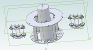
I got the orientation that I wanted thanks don't spend more time on that. Unless you discovered a pot of gold!!!Here's a screen shot to make it clear what I'm meaning!!! The tractors will "crawl" up the palm, which is the big round thing in the middle!!
conservativetrolls
Member
can't thank you enough, for taking the time and making the video!! You were right on in saying that constraining individual bearings is way more that i care about!! Wow learned a ton!!!I took a some more time to go into the assembly in a bit more detail.
Here's a video of that, it may be a bit long winded for some.
HaroldL
Alibre Super User
One last bit of info that may help with rotating the bearings if that's what you want to do.

conservativetrolls
Member
by the way, i watched every second of it!!!!!I took a some more time to go into the assembly in a bit more detail.
Here's a video of that, it may be a bit long winded for some.
conservativetrolls
Member
Do I need to constrain the reference geometry of each new part as I introduce it to the assembly??I just closed with out saving since i didn't want to capture the disarray! It opened fine and appeared to be fine until I "made flexible" Then bearing races lost location!! That appears to me to be an accurate description of the situation at this time!
Also I'm having issues with "swimming displays again!! When I open the original drawing to start assembling the assembly, I tell it to show reference geiomety! When I say "swimming displays" what I mean is that when I attempt to rotate the top ring, which is designed to "rotate" instead of rotating it "swims up and down". At that point everything is on location and in place. If I then hit the "make flexible" button (so it will rotate) then the bearings come apart at that moment!! So obviously I can't "make flexible" I really want to be able to "rotate" as that is major element of the design!!!!
HaroldL
Alibre Super User
Do I need to constrain the reference geometry of each new part as I introduce it to the assembly??
Not necessarily, if the part was created to make use of its reference geometry when added to an assembly then Yes. Generally though you can just use the parts surfaces for constraining.
If you are starting a new assembly then the first part added to that assembly must be constrained to the default planes or origin. As I pointed out when constraining the bearing assembly the inner race was constrained to the default axes of the assembly model then the outer race was constrained to the inner race using reference geometry planes for the coincident and curved surfaces for the concentric.
conservativetrolls
Member
Harold, when I opened a bearing in a separate window, I could NOT get it to show any geometry. It would not let me constrain races with simple constraints. When attempting to do that it would say target no longer available?????

conservativetrolls
Member
Harold i went into "View" Looking far and wide, cannot get it to turn on "reference geometry"
albie0803
Alibre Super User
Either Right click the actual part or its name in the explorer tree, its in the popup menu

Or select the part/s and use the ALT+0 shortcut
Its a part by part action, but you can select multiple parts and then do it. There isn't a single "show all reference geometry" action.
Or select the part/s and use the ALT+0 shortcut
Its a part by part action, but you can select multiple parts and then do it. There isn't a single "show all reference geometry" action.
HaroldL
Alibre Super User
Here's a short video that may help;

conservativetrolls
Member
That did thanks ever so much!!!!
By the
By the