Recent content by steveastro
-
S
Traced image as the basis for an assembly
I COULD, but I was trying to avoid that, to ensure complete synchronisation with the underlying image.- steveastro
- Post #3
- Forum: Using Alibre Design
-
S
Traced image as the basis for an assembly
I am trying to use a traced, scaled image as the basis to build multiple components for a boat model. I can create a tracing image in a new assembly. My plan had been to create a part in the assembly, then edit the part within the assembly, and trace it off the tracing image. When I try though...- steveastro
- Thread
- Replies: 4
- Forum: Using Alibre Design
-
S
Best approach for this part
Ah ! No, but that looks like make the sort of approach I was thinking of. Thanks Stefan.- steveastro
- Post #13
- Forum: Using Alibre Design
-
S
Best approach for this part
Whilst the conversation is interesting and informative, its seems to me, that the simplest way to do this would be a mechanism to automatically use a master sketch as the foundation for the works on the part, and there doesn't appear to be a mechanism for it.- steveastro
- Post #10
- Forum: Using Alibre Design
-
S
Best approach for this part
Revolves are my preferred way of working with parts like this. I find it easy to visualise.- steveastro
- Post #8
- Forum: Using Alibre Design
-
S
Best approach for this part
I too find it a PITA when the origin of a new part is displaced like this, but it seems fundamental to the arrangement of parts in an assembly that stays properly constrained.- steveastro
- Post #7
- Forum: Using Alibre Design
-
S
Best approach for this part
Yes, Top Down, there is a complex optical layout which affects the relative positions of the lens, mirrors and focal plane of the system, and which is spreadsheet driven.- steveastro
- Post #5
- Forum: Using Alibre Design
-
S
Best approach for this part
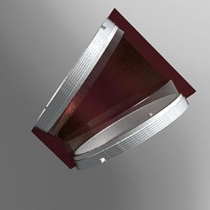
I've attached what is a special lens cell for an optical project. If someone would like to look, at its heart is a sketch tied to a 2D arrangement of lenses tipped and shifted to each other. There is no single rotation of cut that would make this, so the second and third sketches are rotated...- steveastro
- Thread
- revolve
- Replies: 12
- Forum: Using Alibre Design
-
-
S
Working with large hexagonal mesh
Will look at your suggestions. Thanks. Never have got to grips with "topology pattern" - now might be the time ! I tried a large sketch, and I tried feature pattern. I think there is probably a sweet spot somewhere, but I didnt find it. I also tried removing all the consraints in the sketches...- steveastro
- Post #11
- Forum: Using Alibre Design
-
S
Working with large hexagonal mesh
We had a smaller part (this is part of a family) made last week very economically with a fibre laser. The laser was running at 400 IPS. Each part which you can reckon being 9 x12 " or so, took less than 10 minutes. The final profile for the part ran at 1200 IPS. The final cost of the part was...- steveastro
- Post #10
- Forum: Using Alibre Design
-
S
Working with large hexagonal mesh
Hi Lew Here's a sample of the piece.Its only a small sample. The mesh has to be in-phase across all the filled pockets, so I have made a piece of hex material as a separate part which I cut out with a sketch of all the pocket outlines, then boolean unite into the model of the part.- steveastro
- Post #3
- Forum: Using Alibre Design
-
S
Working with large hexagonal mesh
I have a sheet metal part which, when its finished, will be perforated with 6.5mm AF hexagonal mesh - the part is fairly big, about 450mm x 450mm, and my mesh keeps breaking Alibre to the point of crashing. How can I improve the performance ?I've tried to use more sketches of meshes, and fewer...- steveastro
- Thread
- Replies: 11
- Forum: Using Alibre Design
-
S
Sheet metal tutorials
Harold, I didn't realise unbend was as useful as you show it ! Lew, thanks, I'll play with Harold's files and see if that fixes my current issue. Steve- steveastro
- Post #5
- Forum: Using Alibre Design
-
S
Sheet metal tutorials
Are there any decent tutorials on using the Sheet metal tools ? I have a part with a long edge (say 150mm) from which I need to have two narrower flanges, say 25mm long each, one 20mm from one end of the long edge, the other 60mm from the same edge. Every time I have made a flange and then...- steveastro
- Thread
- Replies: 4
- Forum: Using Alibre Design