You are using an out of date browser. It may not display this or other websites correctly.
You should upgrade or use an alternative browser.
You should upgrade or use an alternative browser.
Best way to generate gears in Alibre Design Expert ?
- Thread starter MikeD
- Start date
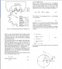
I haven't tried it yet, but I found the formula to draw involute gear shape at page 10 of this document.
I downloaded from this site.
http://www.khkgears.co.jp/en/gear_technology/index.html
I downloaded from this site.
http://www.khkgears.co.jp/en/gear_technology/index.html
Attachments
NateLiquidGravity
Alibre Super User
Are you going to need custom gears or to build your own gears? If not then I'd suggest downloading them from a manufacturer catalog.
OTE_TheMissile
Alibre Super User
You'd be doing a service to humanity though...ugh, I positively HATED the Gears chapter of my Mechanisms class in collegeindesign said:Man if I get the time this would be great to create an addon. Maybe I should start looking into it but it would be pretty intense to get it right with tolerance values and all.
OTE_TheMissile
Alibre Super User
How do you say "Friggin' Sweet!" in German? 8)
Ralf
Alibre Super User
Friggin Sweet :lol:
Ralf
Alibre Super User
Number of gear "teeth" z1 and z2
z1 = Pinion size = small gear
z2 = Wheel size = large gear
mn = ( Modul Normal ) mt = mn/cosß
(beta) ß = 0 and the Modul is m ( mn = mt = m )
(beta) ß = 0 -> cos 0 = 1 -> mt=mn/cos0 = mn/1 = m
If ß > 0 = automatic mt
x1 = profile postponement -> pinion = small gear
x2 = profile postponement -> wheel = large gear
Excuse please my "Google" English, but I have not enough time at the moment...
.
Attachments
Very nice but I think you may missunderstand the request.
I have customers who send prints with an involute where there is a dimension over pins. This pin is a cylinder placed in the teeth and measured over the outside. The other software we currently use is called mechanic and it was originally designed for wire edm cad/cam. The gear module is not provided with their newer software which means we can no longer update. :shock:
I have customers who send prints with an involute where there is a dimension over pins. This pin is a cylinder placed in the teeth and measured over the outside. The other software we currently use is called mechanic and it was originally designed for wire edm cad/cam. The gear module is not provided with their newer software which means we can no longer update. :shock:
Ralf
Alibre Super User
Ah Ok, yes I think I understand.
I think it will already work.
At this moment we are ready for 2D.
But I will this Add-on => "have" in 2D and 3D with a new dialog box and with many input possibilities.
2D for special geometry`s and 3D for the quick visualization.
At the moment the dev. team has a lot of work, so we do not want to bother Travis... :wink: with our questions.
Astro Scott
New Member
ralf3 said:Please give us some weeks/days :wink:
This looks very good! how soon before we see it
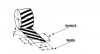
 . Will this have the ability to do helical gears?
 Best Regards,
Scott
2GB, GTX260, E8500 3.16GHz, Vista 32bit, AD V11
Oldbelt
Alibre Super User
Dear tchar
See my parametric gear design at :
download/file.php?id=4472
I have used those templates for several gear designs.
kind regards
Oldbelt
Do it right first time.
See my parametric gear design at :
download/file.php?id=4472
I have used those templates for several gear designs.
kind regards
Oldbelt
Do it right first time.
protarawizard
Member
Hi,
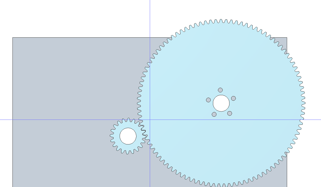
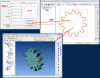
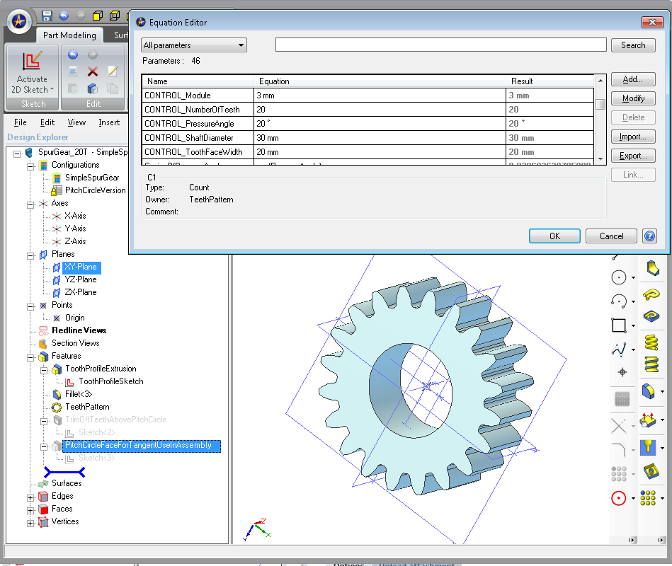
Here is my "improved" version of the Spur Gear model posted by Oldbelt. This version has tried to "englishise" the wording plus has 4 "CONTROL" values in the EquationEditor to control the layout.
Idea is by changing the values for "CONTROL_Module", "CONTROL_NumberOfTeeth", "CONTROL_PressureAngle", "CONTROL_ShaftDiameter", "CONTROL_ToothFaceWidth" the model will update to suit.
In the project tree there are a couple of "suppressed" sketches; these (when enabled) change the model by trimming the teeth above the pitch circle; and/or adding in a pitch circle solid ring; both of which I found useful in assembly placement. That said, once I gained confidence the model was doing the right thing, I found all it was way better to add the "PitchCircleRadius" values (from the EquationEditor) for a pair of gears and applying the total to an AssemblyConstraint that set the distance between the shaft centers; this worked well and allowed movement of the likes of bearing blocks around in the Assemby while retaining the correct spacing.
[Edit] I had another look at an assembly of mine that had a gear pair; my finding was that the spacing between the gears (in my projects anyways) was controlled by applying the distance (attained from adding the pair of "PitchCircleRadius" values) as a spacing of the shaft holes on the backing plate in the BackingPlate PRT file. The shaft holes in the gears are then aligned to the shaft holes in the backing plate within the assembly.
[Edit] If the suppressed "PitchCircleFace" objects in the Gear PRT files are enabled then the Gears can be mated together using an OutsideTangent contraint in the Assembly. The gears will then happily roll around each other if dragged within the assembly.
Cheers,
Norman
Attachments
RCH_Projects
Alibre Super User
Really, really great!
Now, if only; http://forum.alibre.com/viewtopic.php?f=1&t=11154&p=66524&hilit=+gear#p66524
For the "pitch circle solid ring" is that an outside tangent constraint?
Now, if only; http://forum.alibre.com/viewtopic.php?f=1&t=11154&p=66524&hilit=+gear#p66524
Max said:*leak* - Gear constraints will be in Alibre Motion 2.0 (in AD 2011).
For the "pitch circle solid ring" is that an outside tangent constraint?